 Kody Alan Rogers
The PCB for this project is stored here: https://github.com/PhysicsUofRAUI/Decorations/tree/main/tlc555cp_easter.
0%
0%
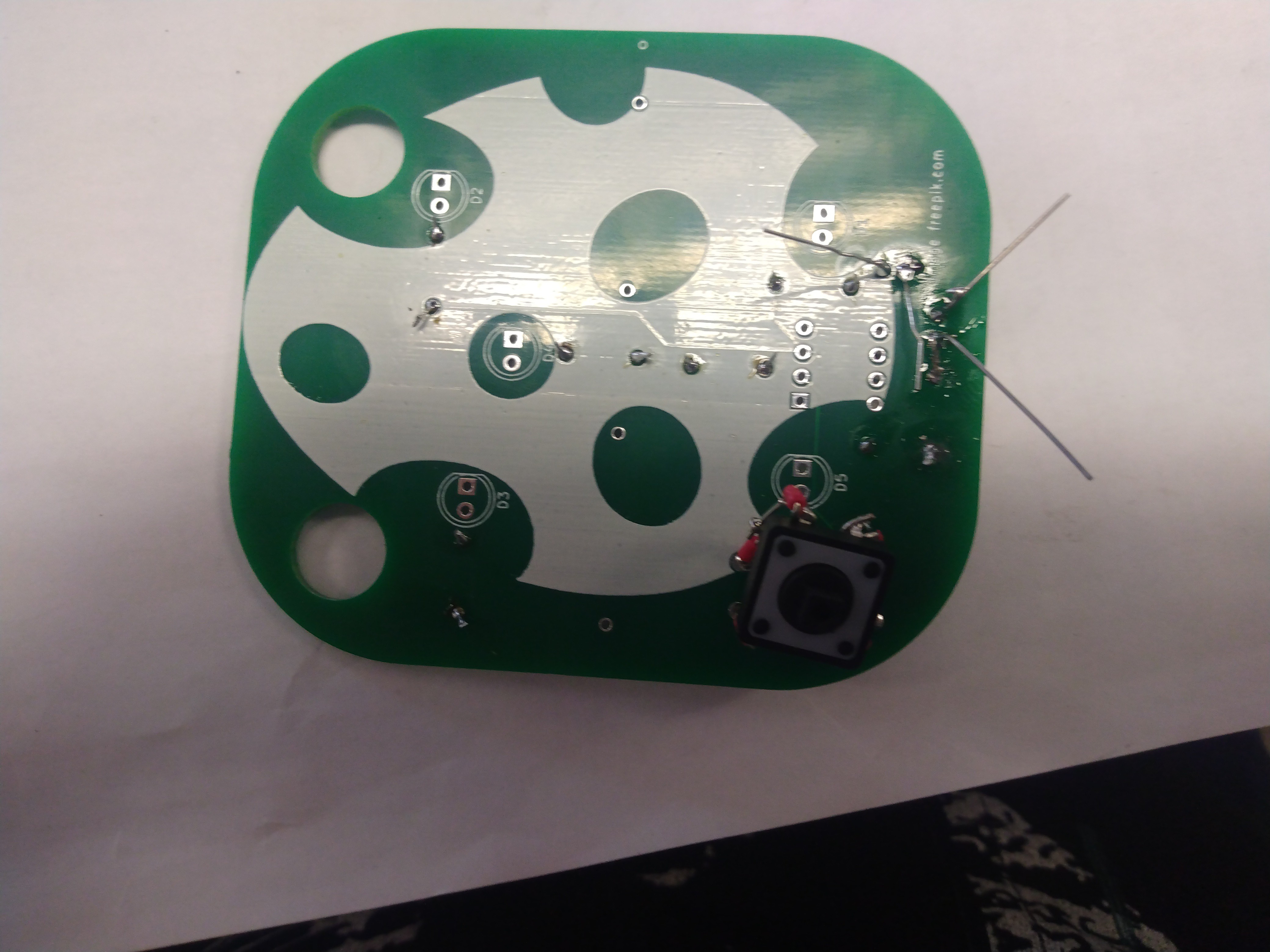
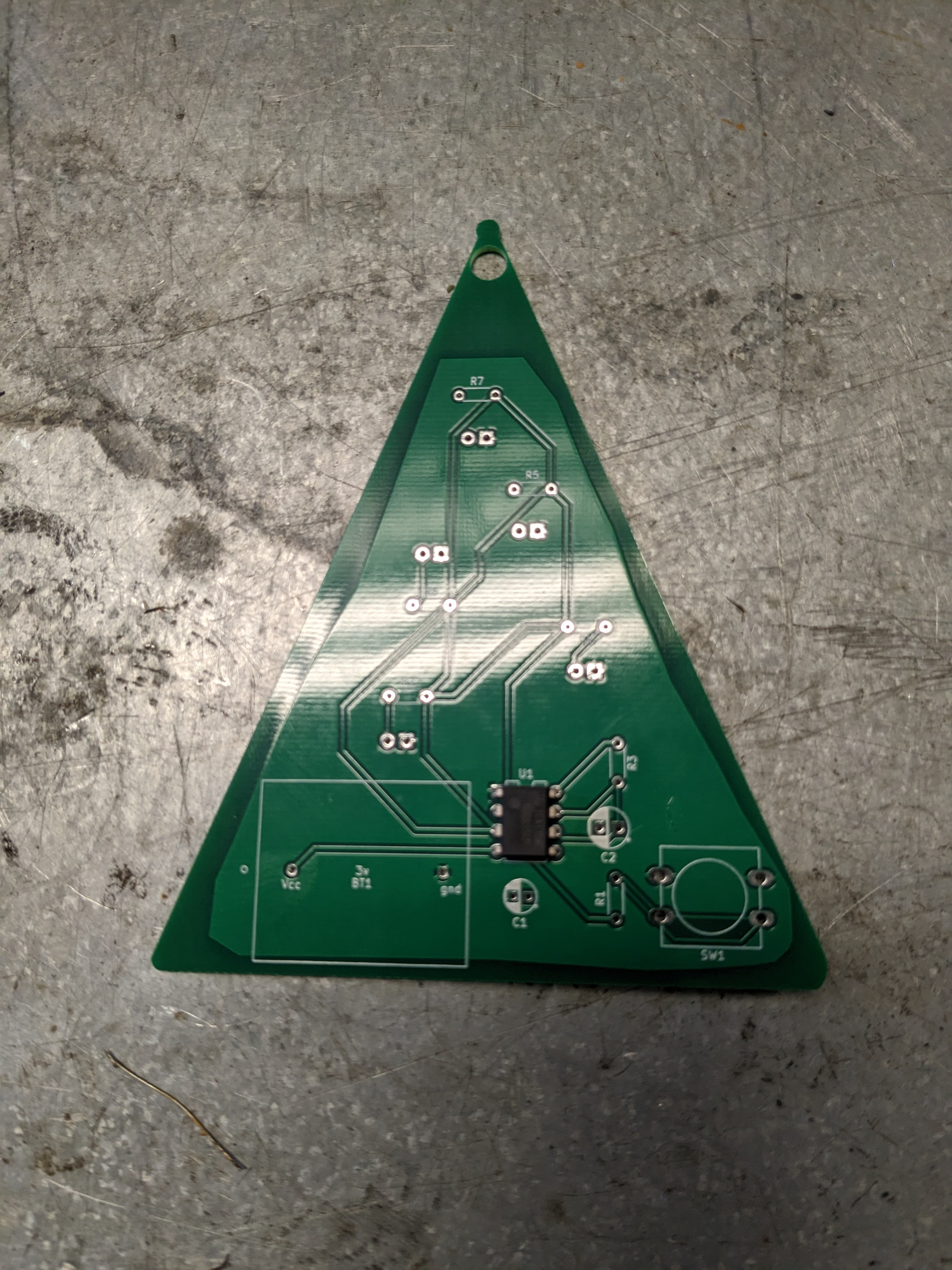
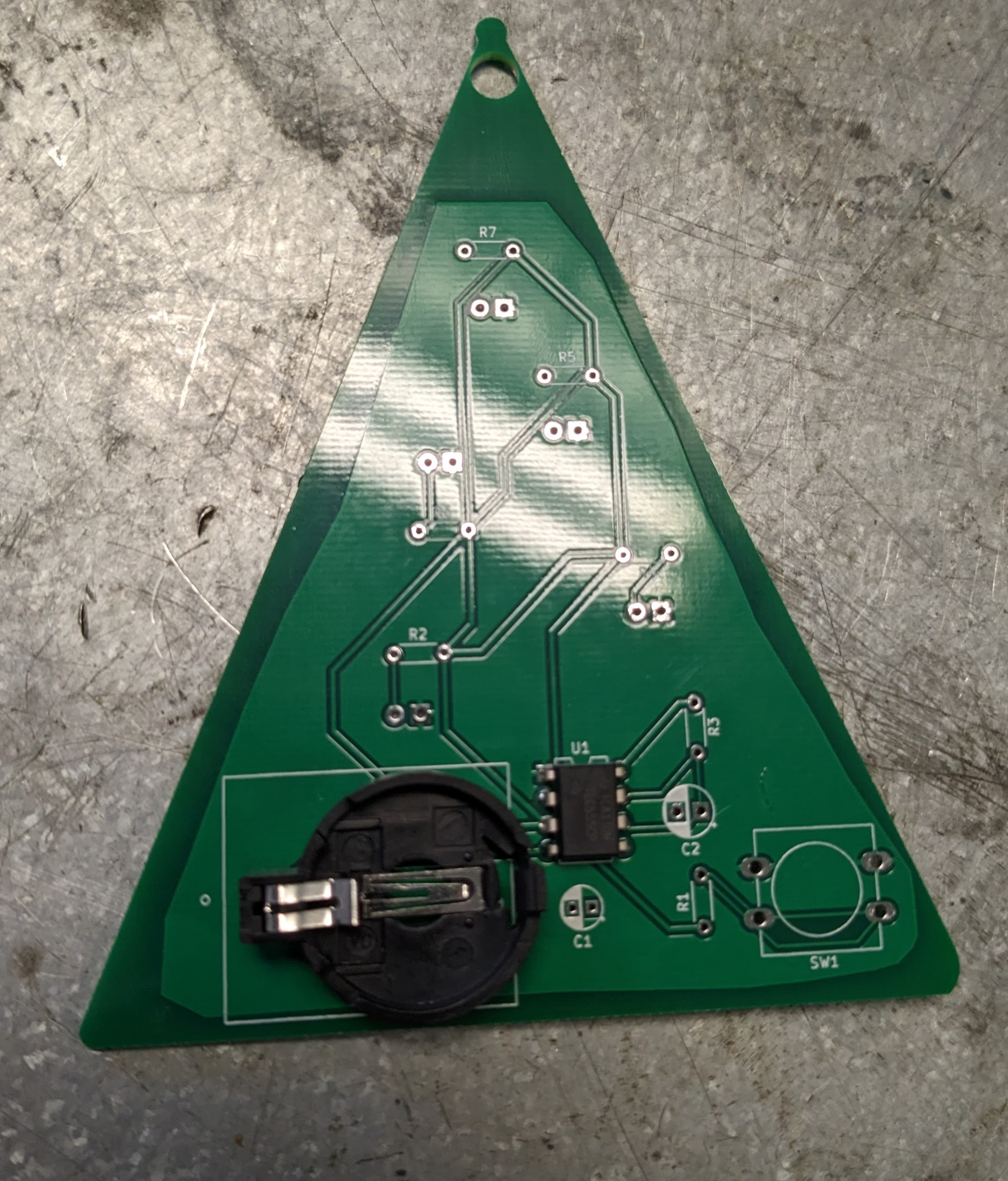
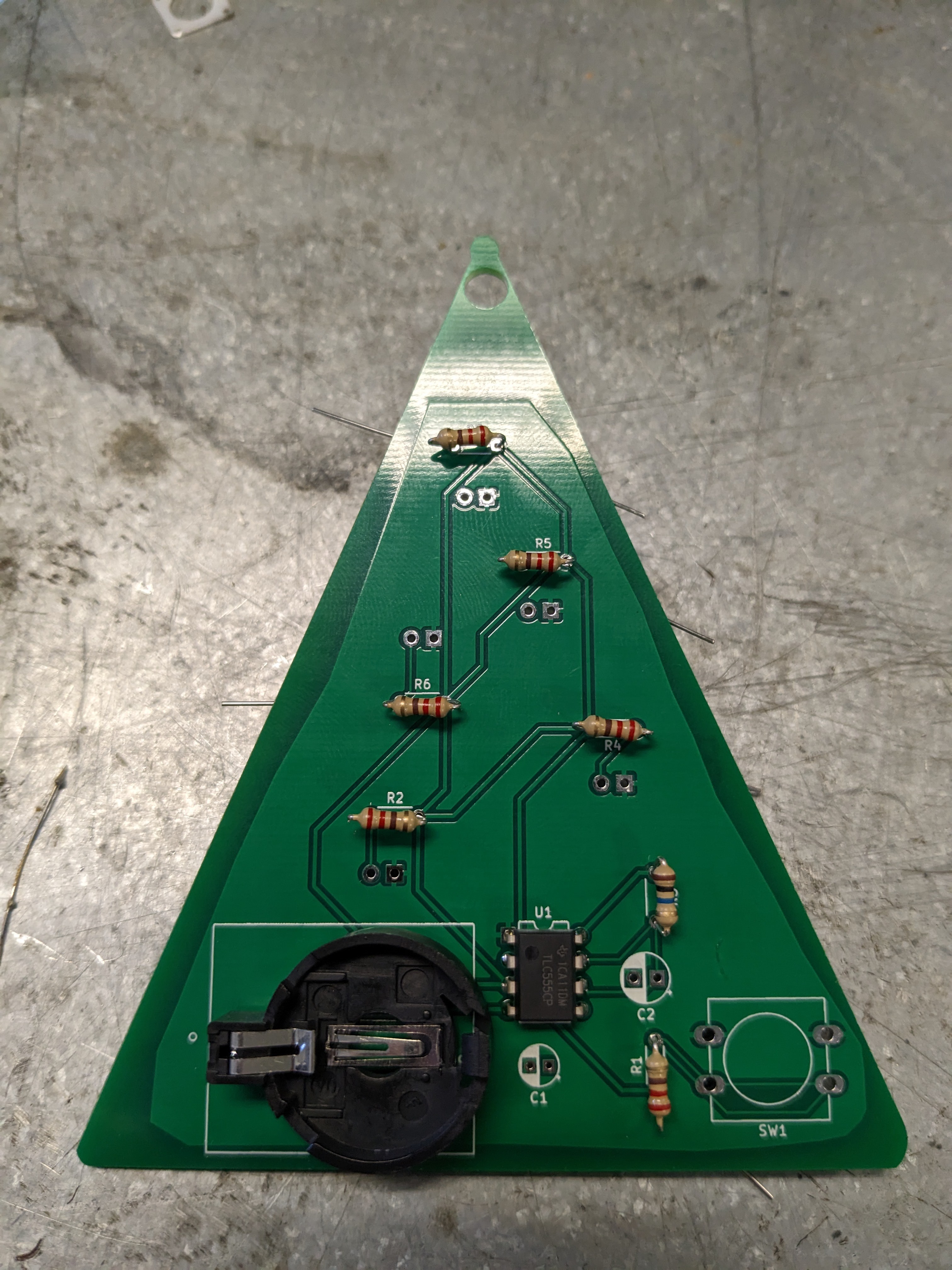
555 Timer Decorations (Monstable)
This project shows how to make simple light-up decorations with a 555 timer.
Become a Hackaday.io member
Already have an account? Log in.
Just one more thing
To make the experience fit your profile, pick a username and tell us what interests you.
Pick an awesome username
hackaday.io/
Your profile's URL: hackaday.io/username. Max 25 alphanumeric characters.
Pick a few interests
Projects that share your interests
People that share your interests

 Adam Redfern
 PRASHANT KUMAR
 utsourceproduct
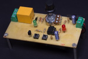
 Electro Guruji