Denys Zaikin
HIGH VOLTAGE: HAZARD OF ELECTRICAL SHOCK.
WARNING: This equipment should be installed, adjusted, and serviced by qualified electrical maintenance personnel familiar with the construction and operation of the equipment and the hazards involved. Failure to observe this precaution could result in bodily injury.
Some parameters of the inverter:
- 12V battery as an input.
- 250Vrms AC output voltage (square wave).
- Output power 200...300W.
- With implemented MOSFETS (IPB027N100) the higher power (up to 500W) can be reached using the proper transformer).
- Input and output are protected with fuses.
- The battery polarity is protected by an anti-parallel diode and fuse.
- Battery under-voltage (11.0V) and over-voltage (14.0V) protection disable the inverter.
- Different 50 Hz transformers 230V to 2*9V (or possibly 2*10V) can be used. Old soviet transformers like TCA-270 or TC-180 can be used.
- Push-pull topology.
- IRS21531 driver.
- The output switching frequency is set around 60Hz to avoid transformer saturation.
- Snubber on the output, a small overshoot.
- Low dv/dt on the output due to transformer leakage inductance that works as a filter together with output snubber, so low EMI noise.
- Schematic and PCB design updated to V2 after bring up.
- The smallest components are in the 0603 case.
Advantages:
- Very simple design.
- A small amount of the components.
- Can be assembled manually spending one evening.
- The load can include AC transformer-based power supply since no DC is generated on the output.
Disadvantages:
- Bulky, big mass.
- High input standby current (~1.5A).
Successfully tested with:
- Phone charger.
- Laptop power supply (charger).
- LED bulbs.
- Weller WX2 soldering station has 50Hz transformer in the power supply.
- Weller W201 soldering tool, purely resistive load, 200W.
- 40W Air cooler LOGIK L40WDF17E.
Bring-up and design notes:
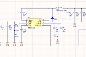
- R1 and C12 provide filtering against low-frequency noise on the DC link and avoid U1 UVLO activated.
- C19 and C14 determine switching frequency can have some temperature instability and thus the output frequency can change a little with device warm-up.
- C16 and C17 have high values (22uF) to filter transients on DC link at startup. The alternative is to increase R121, R14, R16 instead.
- The output switching frequency is set around 60Hz to avoid transformer saturation. A transformer with 2*10VAC (instead of 2*9VA in the current design) may allow a switching frequency 50Hz.
- Connectors can be avoided and wires can be soldered directly into the PCB.
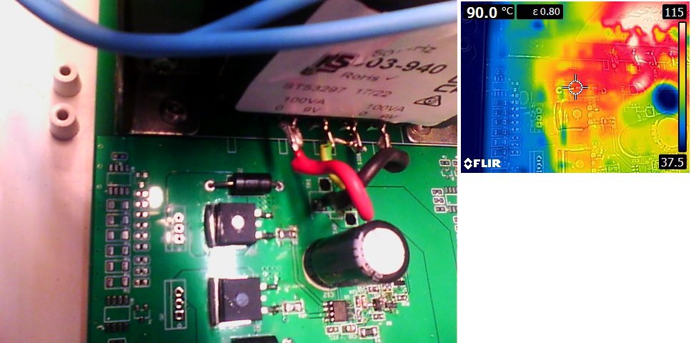
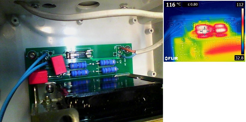
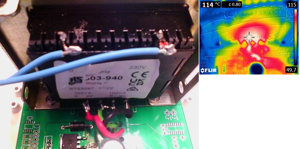
- In V2 of the inverter, some improvements have been implemented along with thermal design improvements. Some PCB tracks increased in width. Outer cooper weight 2oz is recommended.
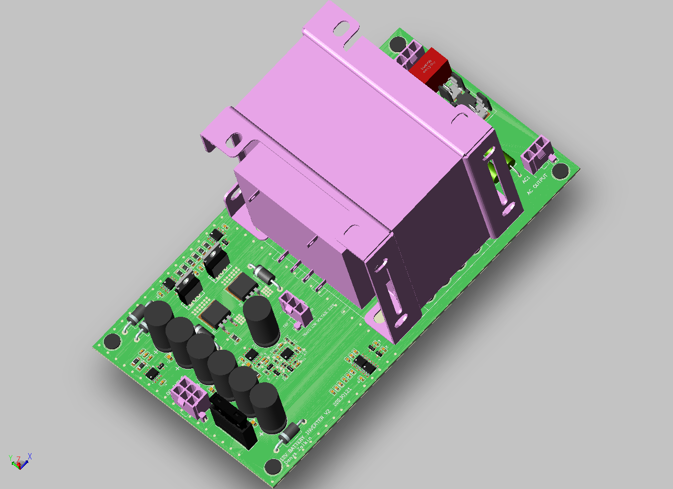
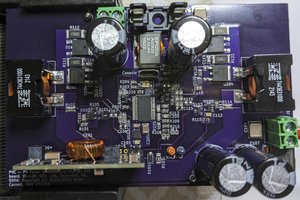
PCB design (3D model from ECAD)
- Some components are not populated, like for possibility to implement TO220 MOSFETs instead of D2PACK.
- Some dummy footprints are placed for possible future experiments and mock-ups.
- A number of holes are placed to have the possibility to mount different transformers.
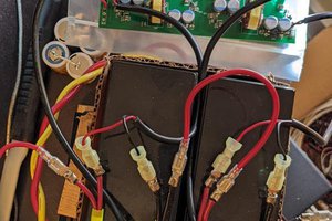
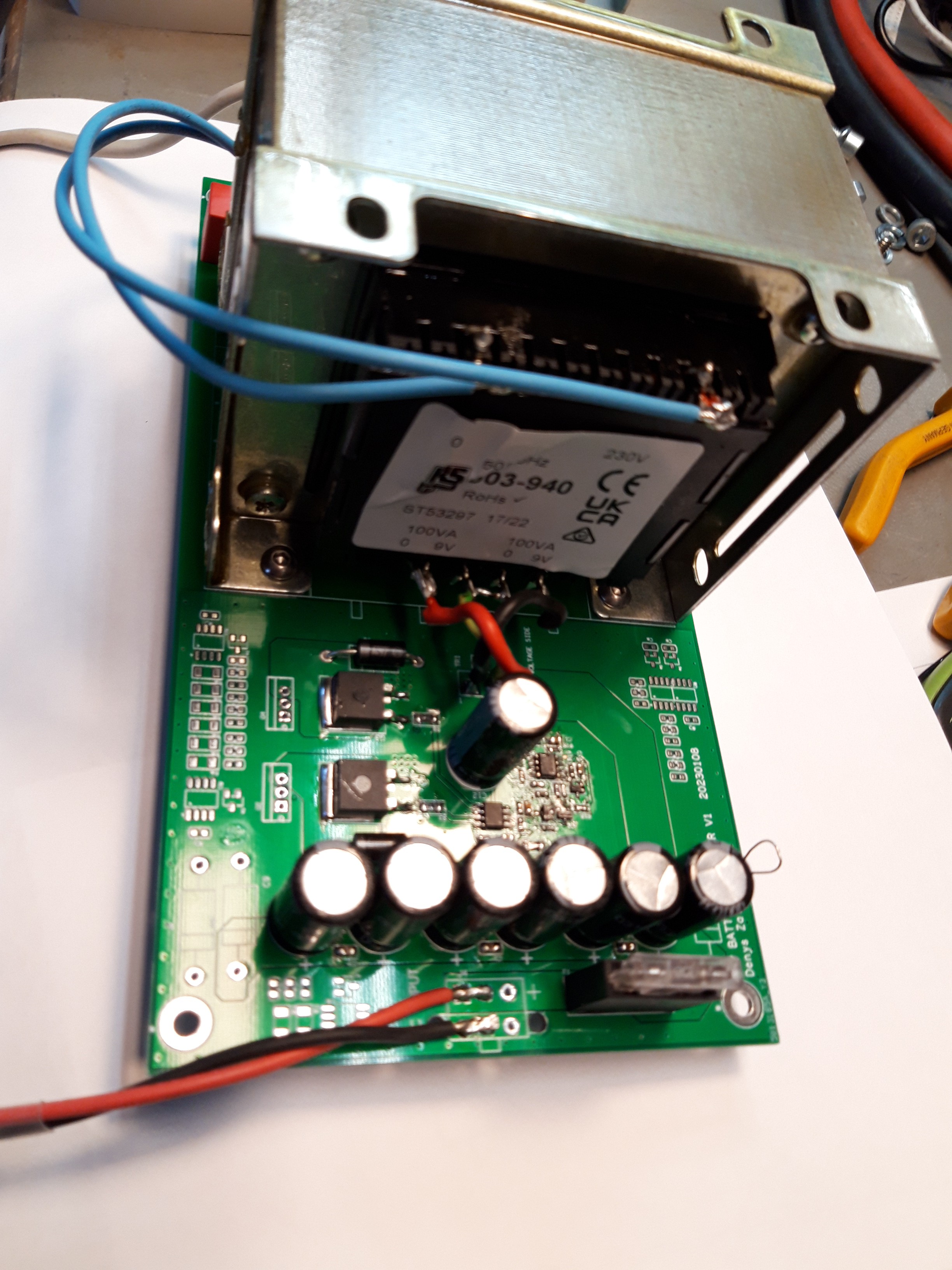
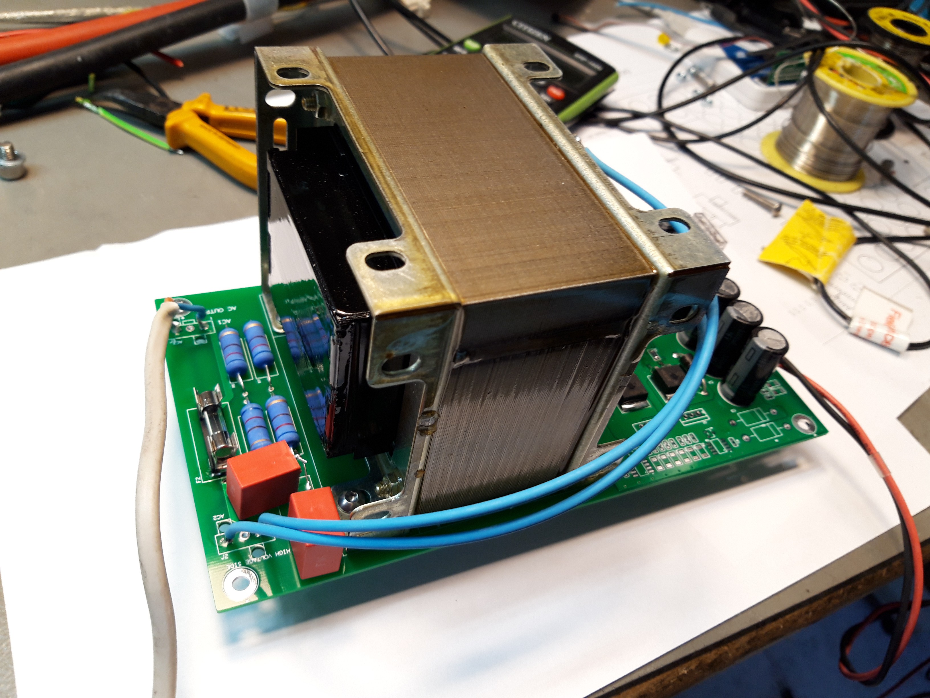
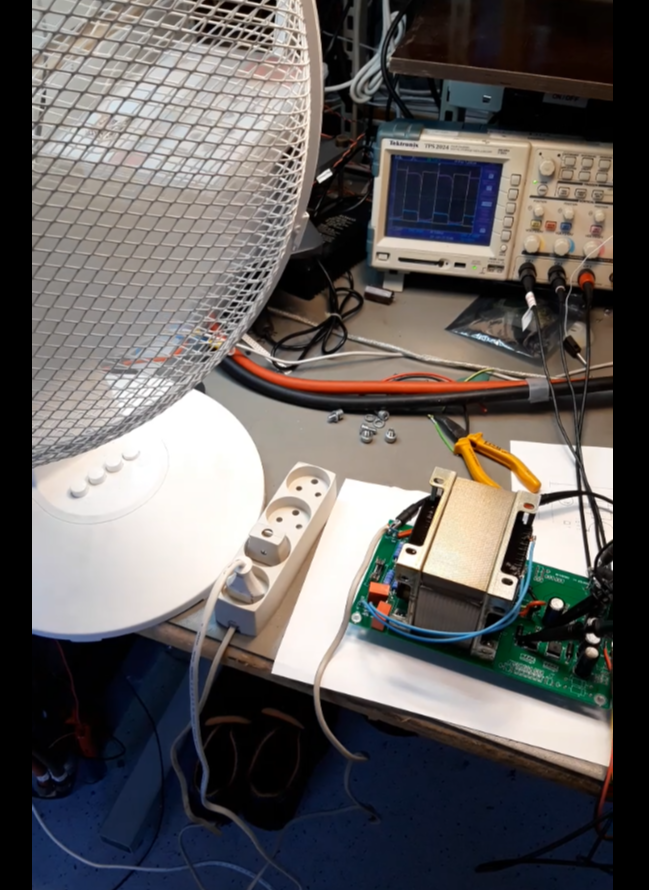
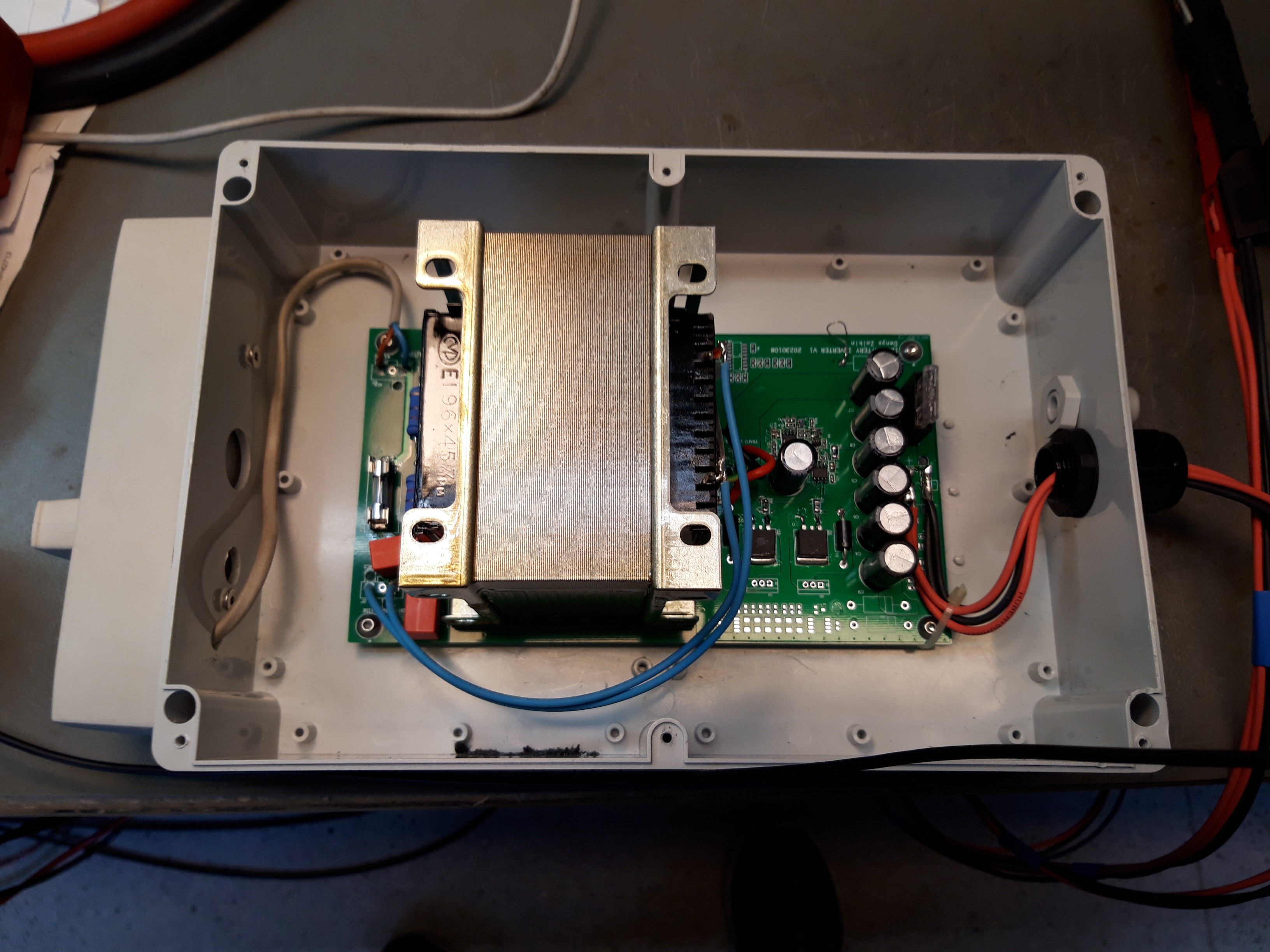
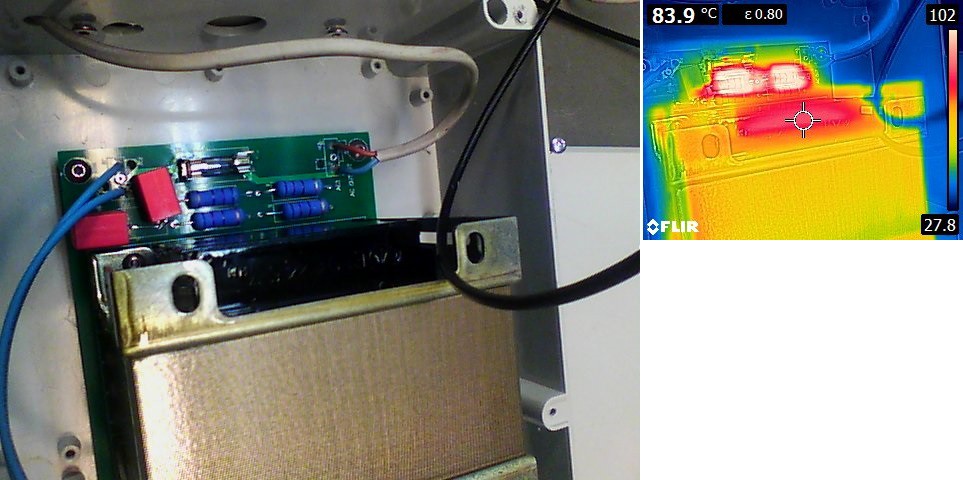
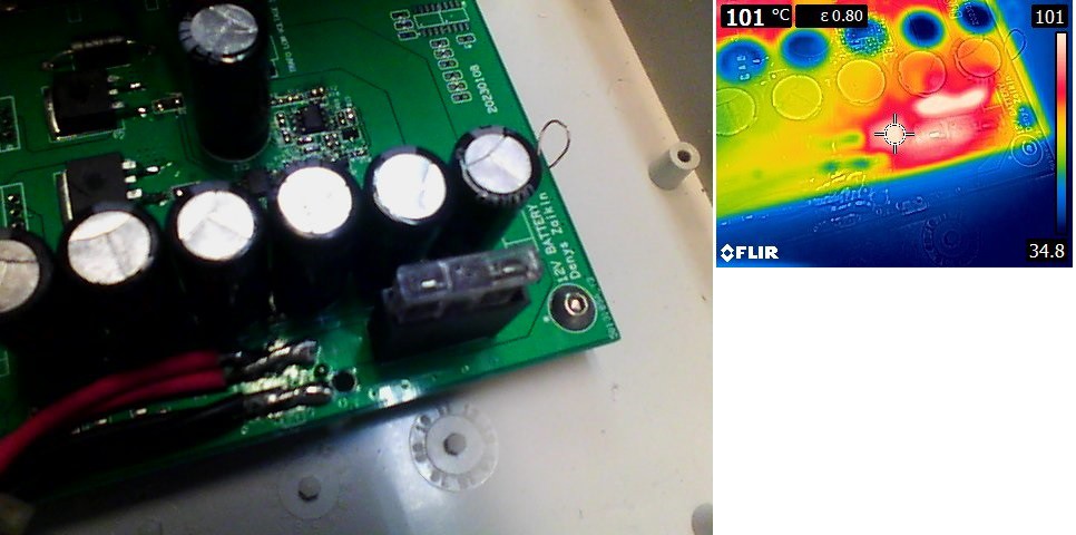
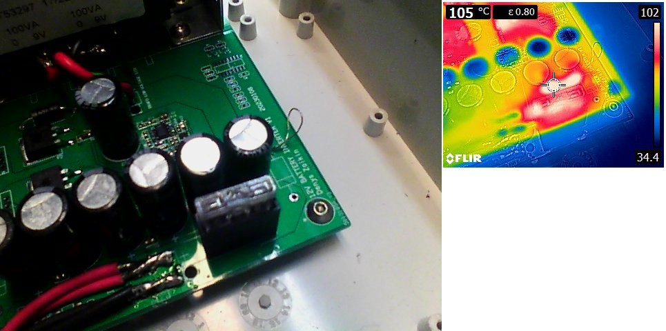
Pictures
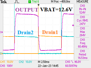
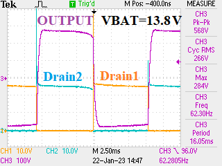
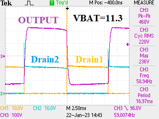
Waveforms
MOSFET drains and output voltage at 200W load:
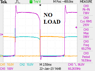
MOSFET drains and output voltage at no load:
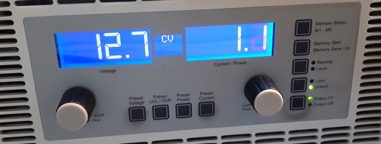
Standby current:
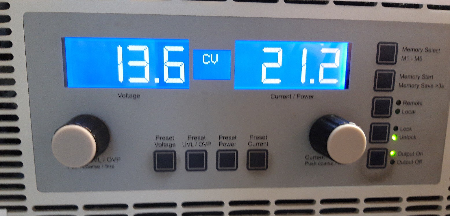
Current at full load (around 200W, Weller W201):
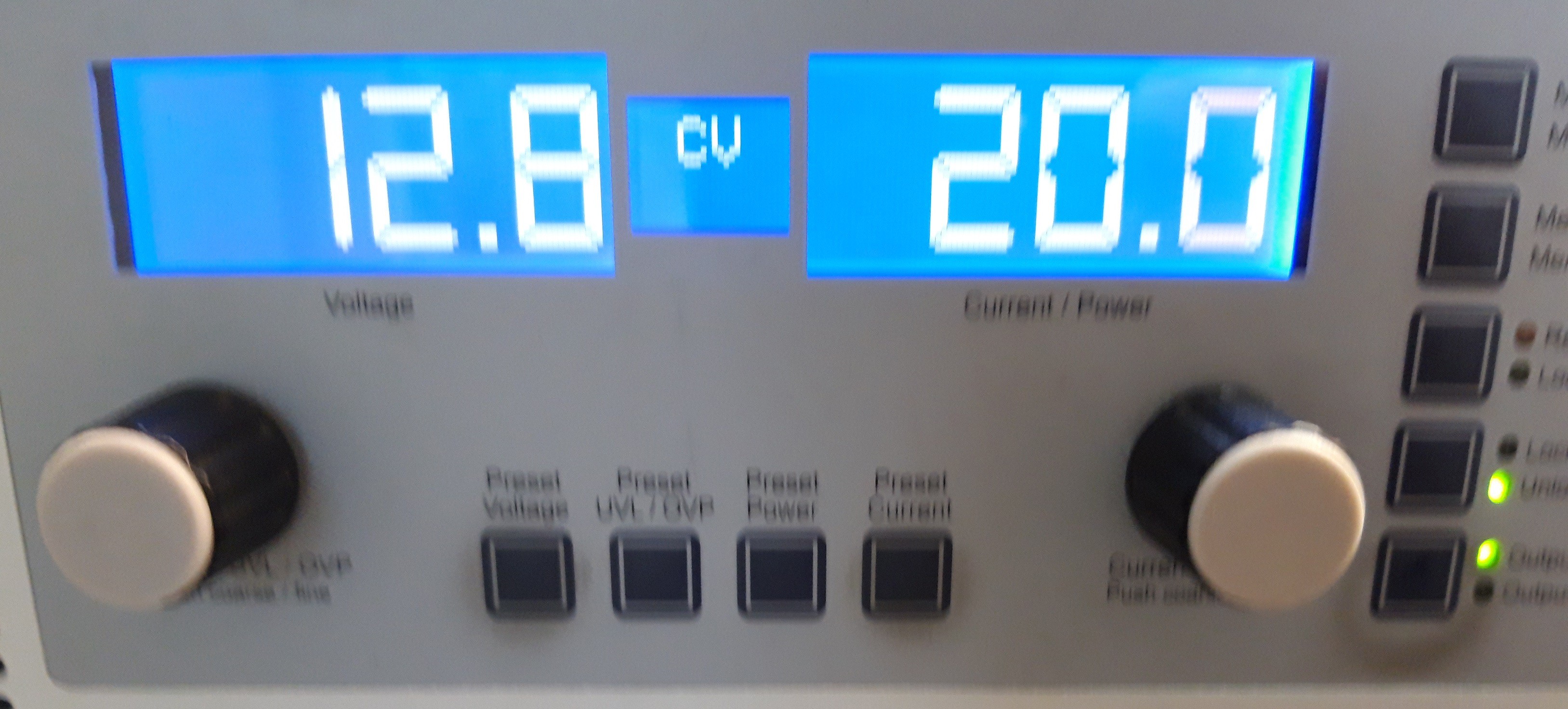
Test with 40 W air cooler (motor inside):
Possible future improvements:
- Add inrush protection (NTC) at the battery side.


 hesam.moshiri
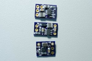
 Bud Bennett