First, here is a list of the needed hardware:
1x Olimex ESP32 POE ISO
1x SparkFun GNSS Receiver Breakout - MAX-M10S (Qwiic)
1x GPS/GNSS Magnetic Mount Antenna - 3m (SMA) also from Sparkfun
1x 4x20 Liquid Crystal Display (LCD)
(one of) a switch that supports POE, a POE injector, or a power supply and micro usb cable,
(optional) 1x momentary button (used to display the Time Server's up-time)
Misc: an available switch port and ethernet cable, some Dupont wires,
2x #4 3/8" screws, 1 small twist tie, filament for a 3D printed case, and solder
.
Why this hardware?
I choose the Olimex board because it has an ethernet connection (much more reliable than WiFi) and the POE cut down on cables running in and out of the case.
Also, I choose the Sparkfun GPS board and antenna as the Sparkfun GPS board had a genuine U-Blox chip in it; plus Sparkfun has a great library and support.
The LCD display was chosen as it just seemed right to me for the job!
.
The (open) source code is posted here:
https://github.com/roblatour/ESP32TimeServer/
The key settings, such as the ESP32 pins used, are in the separate header (.h) file for ease of adoption.
.
Things I learned along the way:
1. https:\\time.is can be used to validate results. Here is a sample:
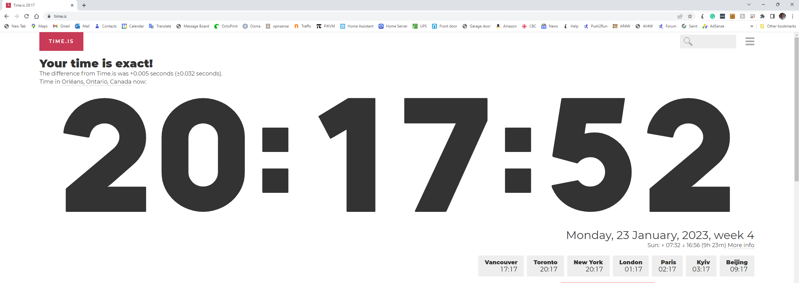
Your mileage will vary. I actually have had even better results than this, but most were not as good. Although once I got the bugs out of my code, tests consistently reported centisecond alignment or better.
2. I used the platformio platform and UI for the first time, having used the Arduino IDE for years. I really like the platformio development experience, it seems to me to be quicker for compiles and deployments, and other VS plugins (like a code spell checker) were available which made the job even easier.
3. I started working with an older-generation GPS module from China. It was stamped with a U-Blox sticker, but I wonder. Also, it did not have a PPS pin. ( What is a PPS pin? Well, it's basically that which provides the beep equivalent to 'At the sound of the beep the time will be eight hours, ten minutes, and fifty seconds ... beep'.) Without the PPS pin, the code was more complex, but I eventually got good results with it using the TinyGPSPlus library all the same. However, the availability of a PPS pin made the coding much easier and the results more reliable so I went for a solution involving a board with a PPS pin.
4. The case I designed myself, and I am while I am no Fusion 360 expert I did also include the .fd3 file along with the .stl file so you can see how I meandered thru the build - and so you could tweak it if you like. It's a very tight fit, but fit it does and nothing should rattle loose. In the end, I also used a little twist tye (not seen in the photo) to secure the GPS board to its position in the case.
5. I did not really stress-test the project - although I did hit it up with two NTP requests at a time and it handled them just fine. Requests are handled within a short period of time and it would be rare (I would think) in my home environment, that the server would get two simultaneous requests.
6. To change your Windows NTP time settings to use the ESP32 Time Server, or to force a time sync in Windows - just google it - there are lots of pages that detail how to do that. However, an alternative for the built-in Windows approach for periodic NTP updates I found and am using this: https://www.meinbergglobal.com/english/sw/ntp.htm (the ESP32's Time Server ip address is entered as part of the setup). I have one older PC that was not getting great results with the stock Windows...
Read more »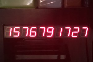
 Dillon Nichols
 Bharbour
 Darian Johnson
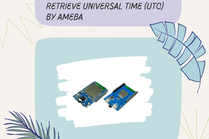
 HYuiii