 G. Rosa
 **** Robotic Arm Pouring a Drink Video ****
It is important to note that prior to assembling the robotic arm that one should endeavor to test each servo separately and to make certain that the horn being used is positioned to either 0 or 180 degrees depending on how the servo is to be placed on the arm and attached to the mounting brackets. During the individual servo testing phase (should one choose to do so), one can use two “for loops” in the program to sweep the servo motor back and forth and help determine the desired position for the horn. I believe that this will help ensure that when writing the “for loops” in the software that all the servos used, will rotate in the same desired direction. Moreover, when testing each servo prior, if the horn does not end up in the desired location, it may be necessary to physically adjust the horn on the servo and test again. All this is done to help set up the desired initial servo setup locations at the beginning of the software. It will also help prevent from having to later take things apart and having to reposition the servo horn(s). I also recommend that when assembling the robotic arm that one servo be included at a time and tested. This can be accomplished by running portions of the program. The claw should be saved for last; making sure that the rest of the robotic arm is working as it should.
Servo control:
It will be necessary to connect both the GND (ground) pin of the Arduino and the power supply together otherwise the robotic arm will not function. And if the servos use more than 300 mA, it is highly recommended to use an external DC regulated power supply in order to avoid damaging the Arduino. In addition, any wires that get disconnected from the bread board or servo may cause the robotic arm to exhibit unexpected or erratic movements. Similar issues can occur if one or more of the servos are not receiving sufficient power.
Arduino software code:
In each of the for loops used, the algorithm instructs the servo motor to move to a particular angle or position with the function write( ). Note that you will need a delay( ) between the commands to give the servo motor some time to move to the set position. It will be common to use the write() function at the start of the program to set the servos (i.e. robotic arm) to the desired starting “initial” position. The Arduino software program itself will have a total of 12 functions each using a “for loop” in order to move one of the servos to a particular/desired position in a very smooth flowing fashion.
HC-SR04 Ultrasonic Sensor:
The hc-sr04 ultrasonic sensor will be set up to communicate with the Arduino program indicating when the robotic arm will become activated to pick up let’s say a desired object (i.e. small block). That is, the software program will include the necessary code in order to have the input from the sensor determine when to run the algorithms that will activate the servos on the robotic arm. In this case, the sonar device will be set up to sense an object 18 to 19 centimeters away from the base of the robotic arm. The ultrasonic sensor will be positioned at the base but will not be required to move with the robotic arm assembly. The robotic arm will not move until an object is placed within the measured linear distance point.
Two 12V DC Regulated Power Supply Units:
Due to the claw (gripper) requiring at least 5 volts when operating, it did not leave sufficient power for the remaining servos to operate. Using only one power supply feeding 6 volts to all the 6 servos often resulted in the claw not opening or closing properly or the other servos not functioning...
Read more »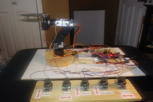
 Aaed Musa
 Boris Landoni
 Luke J. Barker