 Thomas
Supply voltages
The tricky part with IV-6 tubes is that they require several non-standard voltages to operate. Each tube has a grid, eight display segments (including a decimal dot), and a heater filament (you can check out the original datasheet here in Russian). These require the following voltages to operate:
- 25V DC to the grid (pin 9)
- 25V DC to each segment (pins 1-6, 10-11)
- 1.2V DC (or AC) across pins 7 and 8. If you're using DC, treat one of these as the positive and one as the ground (it doesn't matter which is which).
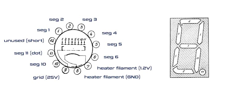
If you are confused about the pinout orientation, simply look on the tube itself for the short pin (unused) and the pin that attaches to the grid. Here is a translation of the relevant voltage and current information from the datasheet:
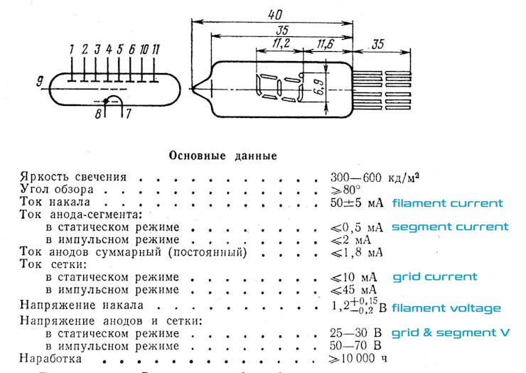
It is not critical that your voltages be exact. I initially ran my grids and segments with 24V, and the heater filament with 1.5V from a AA battery (I later replaced the battery with 1.2V from a buck converter). Whatever you use, be sure all your power supplies share a common ground. The heater filament is actually designed to be run on alternating current, but because there is no easy way to supply 1.2VAC in a DC circuit, most of us just use direct current for this. The downside is that some of the digits may be slightly brighter than others. If you can see the heater filament glowing, you're giving it too much voltage.
The world runs on Multiplexing
This is a great project for learning about multiplexing. Multiplexing is a circuit design technique that significantly reduces then number of inputs and outputs needed to control a display. If we were to wire up each input individually for these three tubes, the circuit would require 29 connections: eight segments per digit + one grid per digit + two shared lines for the filament. This setup would not only be horribly inefficient, but our Arduino Nano also doesn't offer this many outputs. Not to mention the fact that we ultimately want to display data from an external source, which will also requires some of the Arduino pins.
To get around this problem, we and the rest of the civilized world use a trick called "multiplexing" to minimize the number of outputs needed to drive a display. The idea is this: at any given time, only one of the digits is actually illuminated. We cycle through the different digits so quickly, illuminating them one after the other, that the human eye cannot perceive any disruption. In my circuit, each digit is illuminated for five milliseconds (5/1000 of a second), and there is a pause of one millisecond between digits. These intervals are sufficient to create the illusion that the tubes are continuously illuminated.
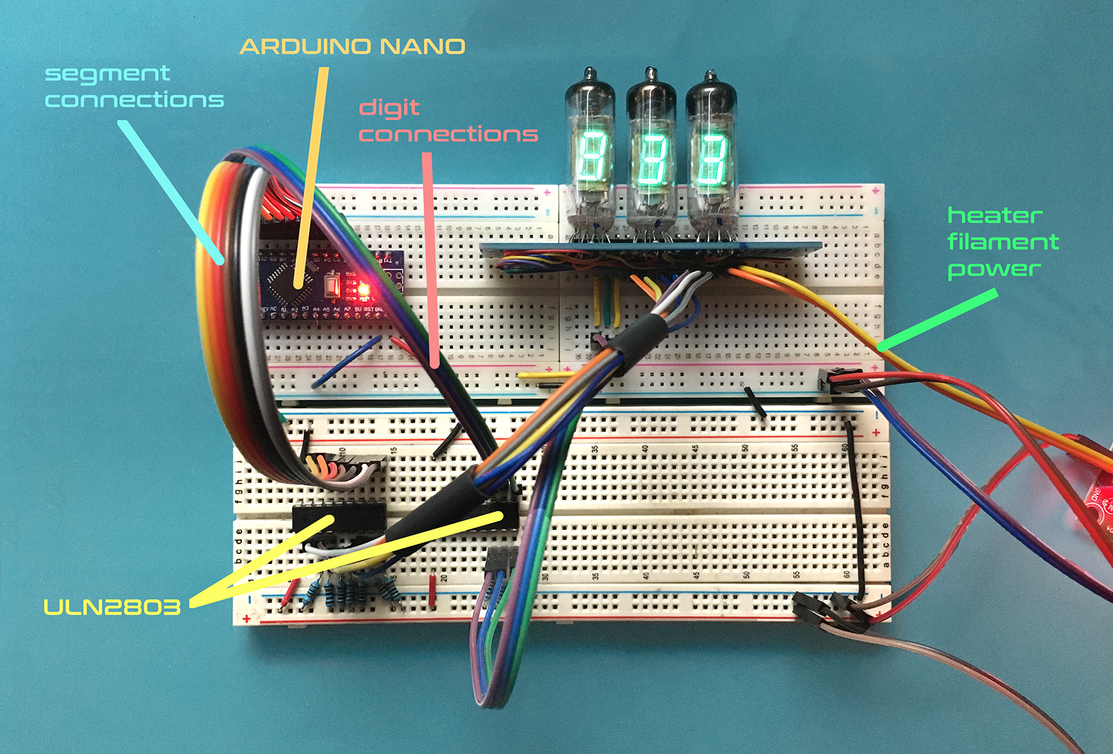
But because the grids and the segments require 25V, they cannot be powered directly from our Arduino. So for the multiplexing to work, we must use a series of transistors acting as switches that push 25V to the tubes when the Arduino gives the command. This "switch" is activated by a LOW signal from one of the Arduino's digital pins to the transistor's base. It's possible to build this circuit with 11 individual transistors (and a lot of patience), but it's much easier to just use a transistor array such as the ULN2803.
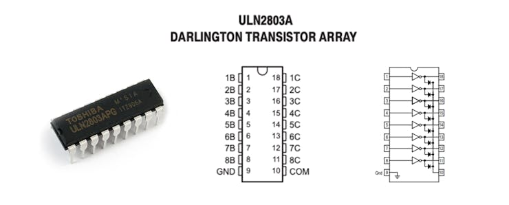
The ULN2803 is the secret weapon that makes multiplexing possible for non-genius makers like myself. To control a display segment, we simply connect an Arduino pin to an input on one side of the ULN2803 chip and connect the output to the corresponding segment of the tube. On the output side we add our 25V supply through a 10K resistor:
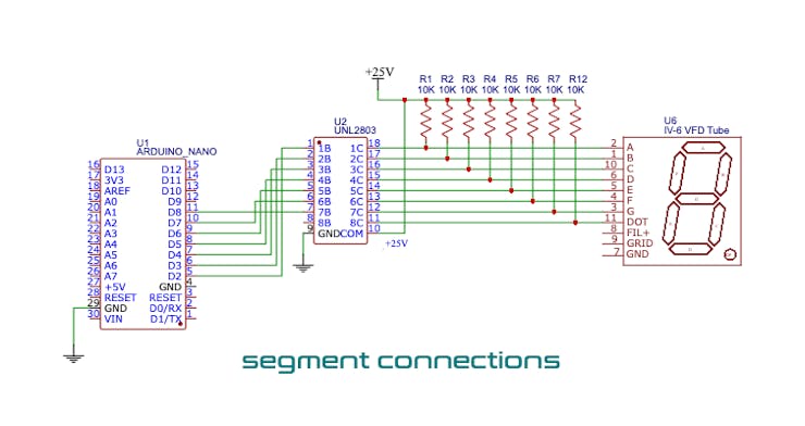
We then use a second ULN2803 in roughly the same configuration to control the grid on each of the digits. This allows us to turn each digit on and off during the multiplexing (check out the full schematic below). So with the help of these two transistor arrays, we are able to control three VFD tubes from a mere 10 pins on an Arduino. Pretty cool!
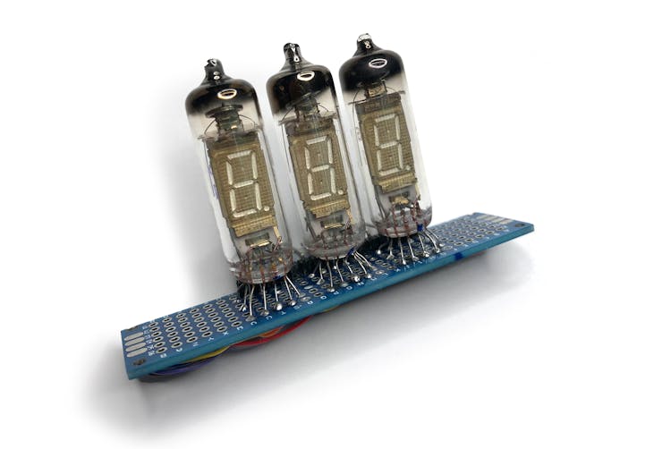
The Display Module
The IV-6 tubes are beautiful when illuminated, but their spider-like leads make them a pain to work with on a breadboard. To make things easier, I built a discrete display module by soldering all three tubes onto a 20x80mm strip of perf-board with a row of 90-degree pins. This allowed me a lot more flexibility in prototyping the circuit, as the module could be plugged directly into the breadboard wherever I needed it. (I borrowed this concept from this awesome blog, which has a ton of great info about VFDs.)
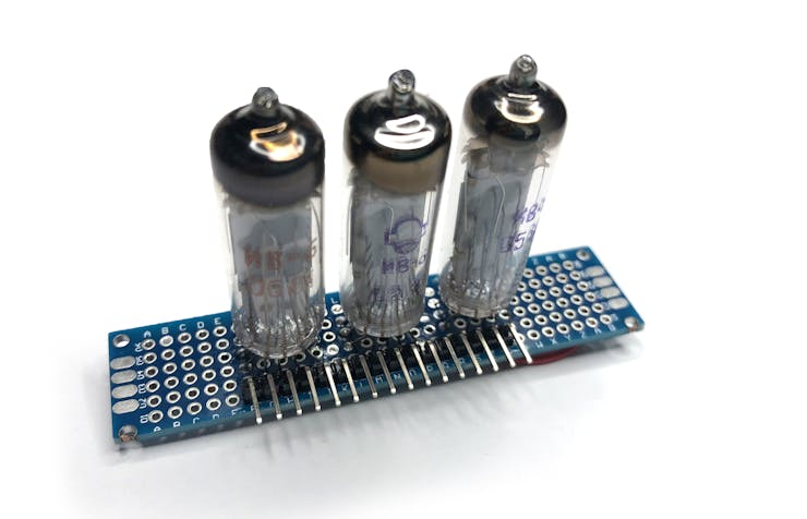
I used 30 AWG solid-core hook-up wire to make all the connections on the back of the board. Because these wires are so thin, I used a digital microscope, a fine tip for my soldering iron, and a syringe of Amtech 559 flux to make things easier. Enameled wire would have probably been a better solution in this context, but the enamel on the wire I had wasn't melting off (even at 450 C degrees!), so I got frustrated and went with transitional insulated wire instead. Before adding the row of 90-degree pins, I sanded off 1-2mm from the edge of the perf board so that the pins along that edge could extend a bit deeper into the breadboard holes. All of this took quite a bit of time and patience, but once the module was up and running it allowed me to focus on the rest of the circuit without constantly having to check and adjust the leads of the VFD tubes.
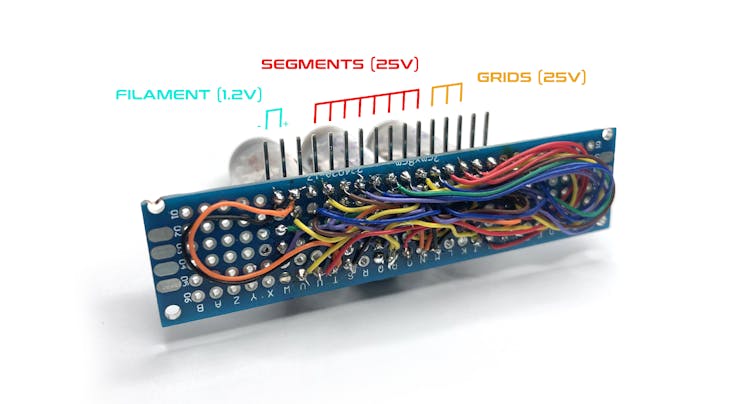
It's important to make sure that the module wiring is correct, or the multiplexing will not work properly. The corresponding segments on each of the tubes must be wired together (e.g., segment A on tube 1 should be connected to segment A on tube 2, and again to segment A on tube 3). The grids for each tube, however, should wired discretely, as you need to be able to turn the tubes on/off independently.
Putting it all together
I ended up using multiple breadboards for the prototype in order to manage all the different voltages. I used a 220VAC to 24VDC power supply to power the grids and the segments, then a 24V-to-8V buck converter for the Arduino power, and a 8V-to-1.2V buck converter to power the heater filaments. All of these different supplies should share a common ground connection.
It's also worth mentioning that the segment assignment on the IV-6 tubes is different from the modern convention where "A" is the top segment, then proceeding clockwise.
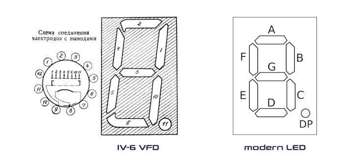
This meant that I had to shuffle the pins around on the cables going from the ULN2803 to the segment pins on the module display. It was necessary here to use independent jumper cables, instead of a ribbon cable (I used some loose pieces of heat shrink tubing to try to keep everything neat and clustered together).
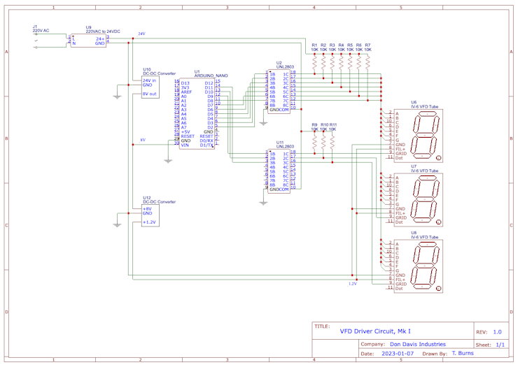
Here's a full schematic of the circuit:
The Code
You can download the Arduino code below. I've tried to leave enough comments in the code itself to help explain everything, but feel free to comment below or DM me if you have questions (or improvements!).
There is one moment in the code that warrants attention here. When I first got the circuit working so that it counts up from zero, I noticed that there was a "ghosting" effect where the unused segments on the tubes flickered faintly. To eliminate this, I programmed a one millisecond delay after the segments have been selected but before the digit (i.e., grid) is activated. Many thanks to @6v6gt over at the Arduino Stack Exchange for helping troubleshoot this problem.
Wrapping up
So there we have it! I'm looking forward to applying this to future projects. If you see ways to improve the circuit or the code, please get in touch and I'll try to incorporate these suggestions into the project log. Many thanks for coming along!