 hesam.moshiri
Nowadays home automation is a trending topic among electronic enthusiasts and even the mass population. People are busy with their life challenges, so an electronic device should take care of the home instead! The majority of such devices need internet or Wi-Fi for connectivity or they don’t offer a user-friendly GUI, but I decided to design a standalone wireless monitoring/controlling unit that can be adjusted using a graphical and touch-controlled LCD display.
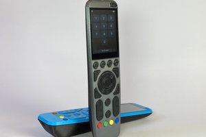
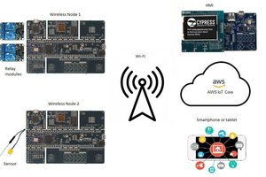
The device consists of a panelboard and a mainboard that communicate using 315MHz (or 433MHz) ASK transceivers. The panel side is equipped with a high-quality 4.3” capacitive-touch Nextion Display. The user can monitor the live temperature values and define the action threshold (to activate/deactivate the heater or cooler), humidity (to activate/deactivate the humidifier or dehumidifier), and ambient light (to turn ON/OFF the lights). The mainboard is equipped with 4 Relays to activate/deactivate the aforementioned loads.
To design the schematic and PCB, I used Altium Designer 23. The fast component search engine (octopart) allowed me to quickly consider components’ information and also generate the BOM. To get high-quality fabricated boards, I sent the Gerber files to PCBWay. I used the Arduino IDE to write the MCU code, so it is pretty easy to follow and understand. Designing a GUI using the Nextion tools was a pleasant experience that I will certainly follow for similar projects in the future. So let’s get started :-)
Specifications
Connectivity: Wireless ASK, 315MHz (or 433MHz)
Parameters: Temperature, Humidity, Ambient Light
Wireless Coverage: 100 to 200m (with Antennas)
Display: 4.3” Graphical, Capacitive-Touch
Input Voltage: 7.5 to 9V-DC (power adaptor connector)


 Max.K
Max.K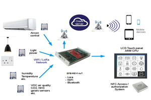
 ensafatef
Nice !