 Matthias Hasenfus
Motor/Servo selection
In my search for a suitable motor I came across the HBS 880 BB MG
brushless servo.
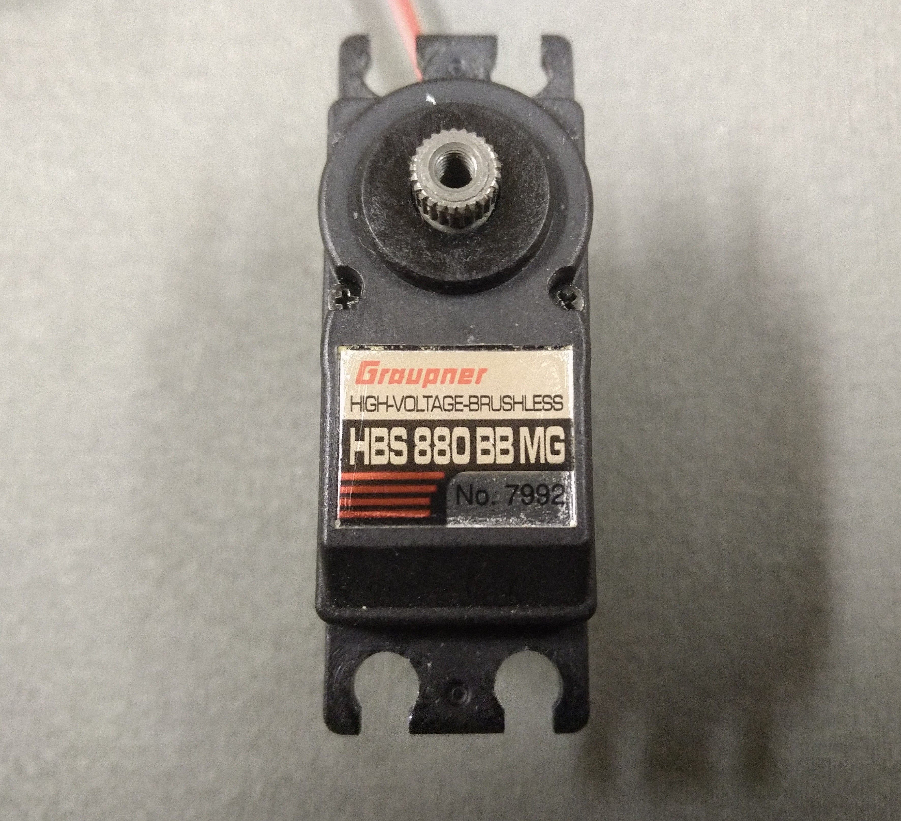
Hobby servos are a good fit for this project since they are relatively cheap, lightweight and already include a gear train. Also the splined output shaft can double as filament drive gear. This particular servo has the following things going for it:
- Brushless (no brush wear and we can use the commutation sensors for control feedback).
- Partially metal gear train.
- 2 ball bearings on the output shaft (we will apply some lateral force after all).
- 1Nm at 7.4V (that’s 333N on the 6mm output shaft, the filament would probably slip earlier).
- 140rpm at no load conditions (enough for 40mm/s retracts).
- 70g (I measured it at 64g).
I was unable to judge if this servo can easily be converted to continuous rotation so I just bought it and found out.
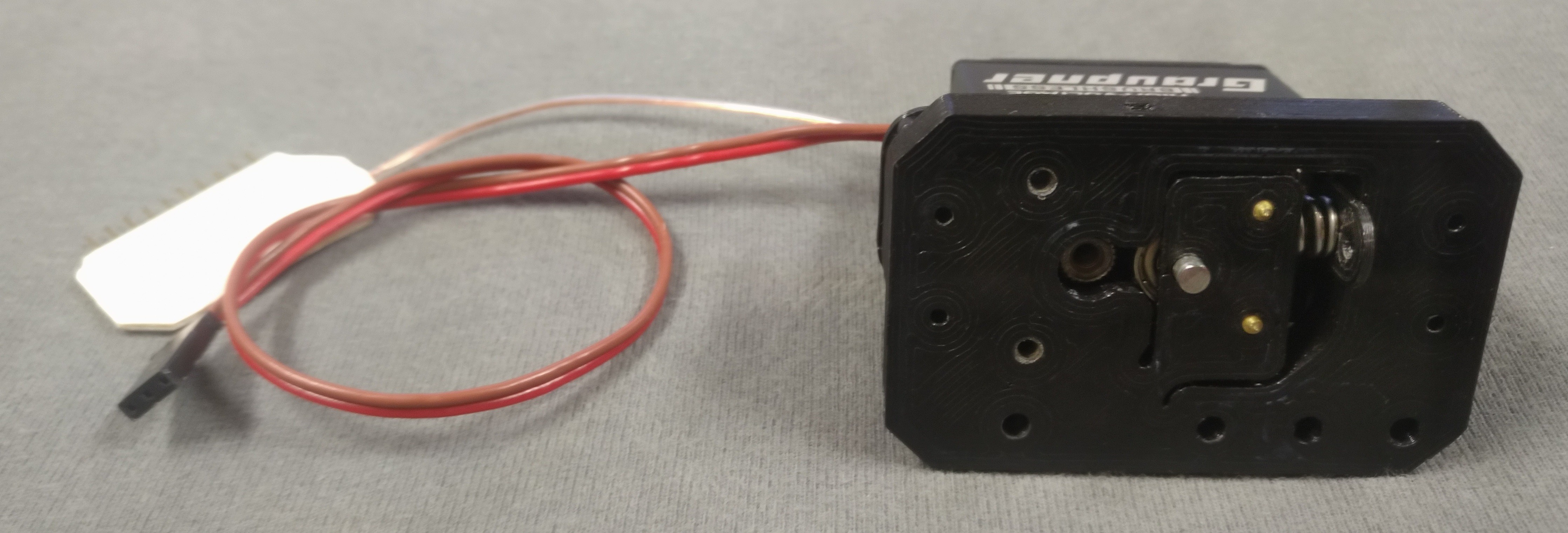
Continuous rotation modification
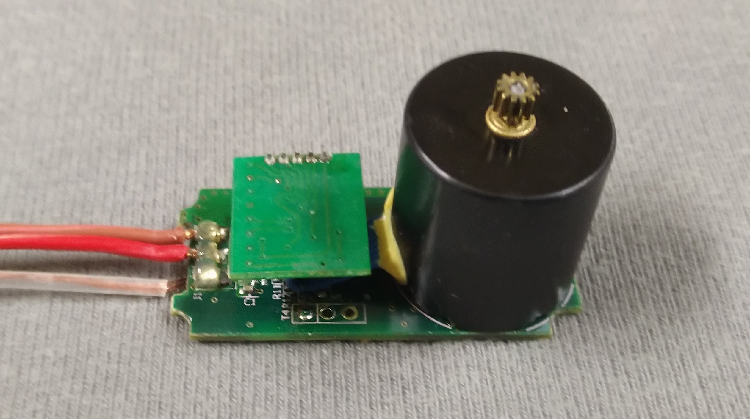
This Hobby servo is quite easy to open up. After removing the 6 visible screws it can be pulled apart. The feedback potentiometer is no longer needed so I simply cut the wires. Now is the first time we see the motor its a mere 17.4mm in diameter and 18mm in length. The three motor phases are soldered directly to the PCB. The wires for the hall sensors go to a little daughter board.
But what we care about now is the gearbox. It comes apart as 4 gears nicely spread across the workbench. I took the liberty to reassemble it for the photo.
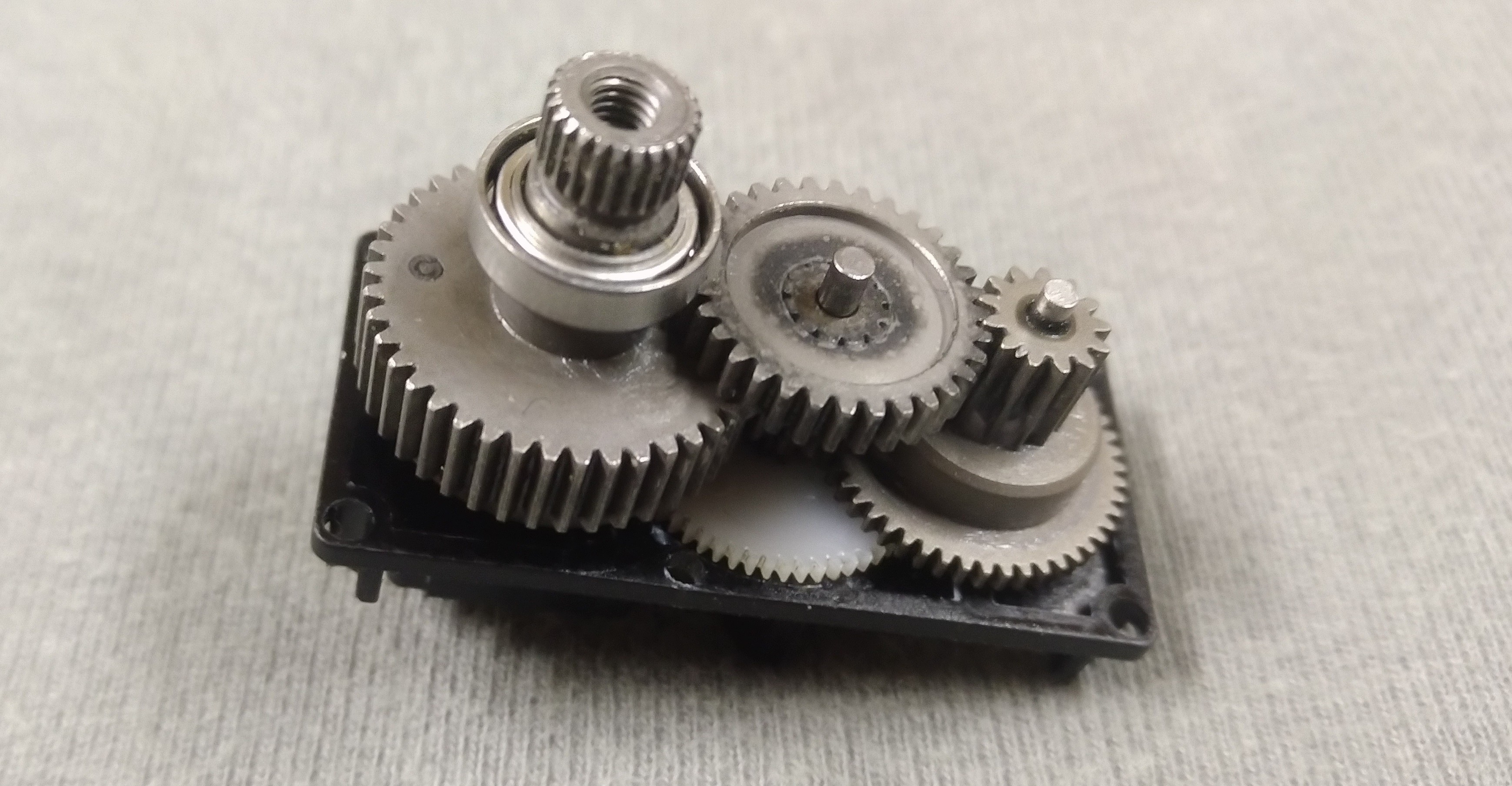
The only things keeping the output gear from rotating 360° are the potentiometer and a small pin embedded in the final gear. The potentiometer can easily be pulled out after unscrewing the single fastener holding it in place.
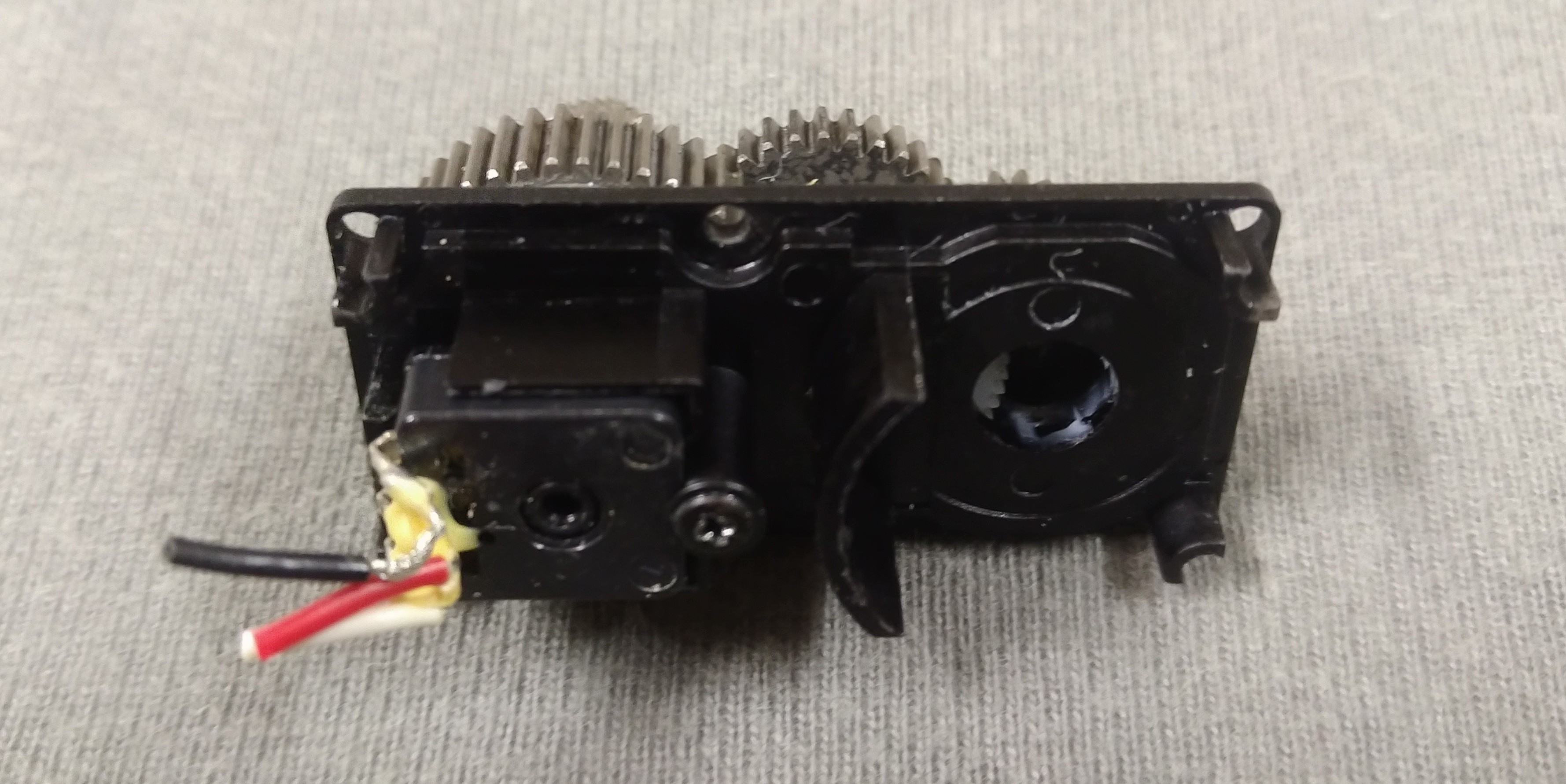
Pulling the pin from the gear didn’t work so I used a saw to cut it
off. A file works for removing any remaining unevenness.
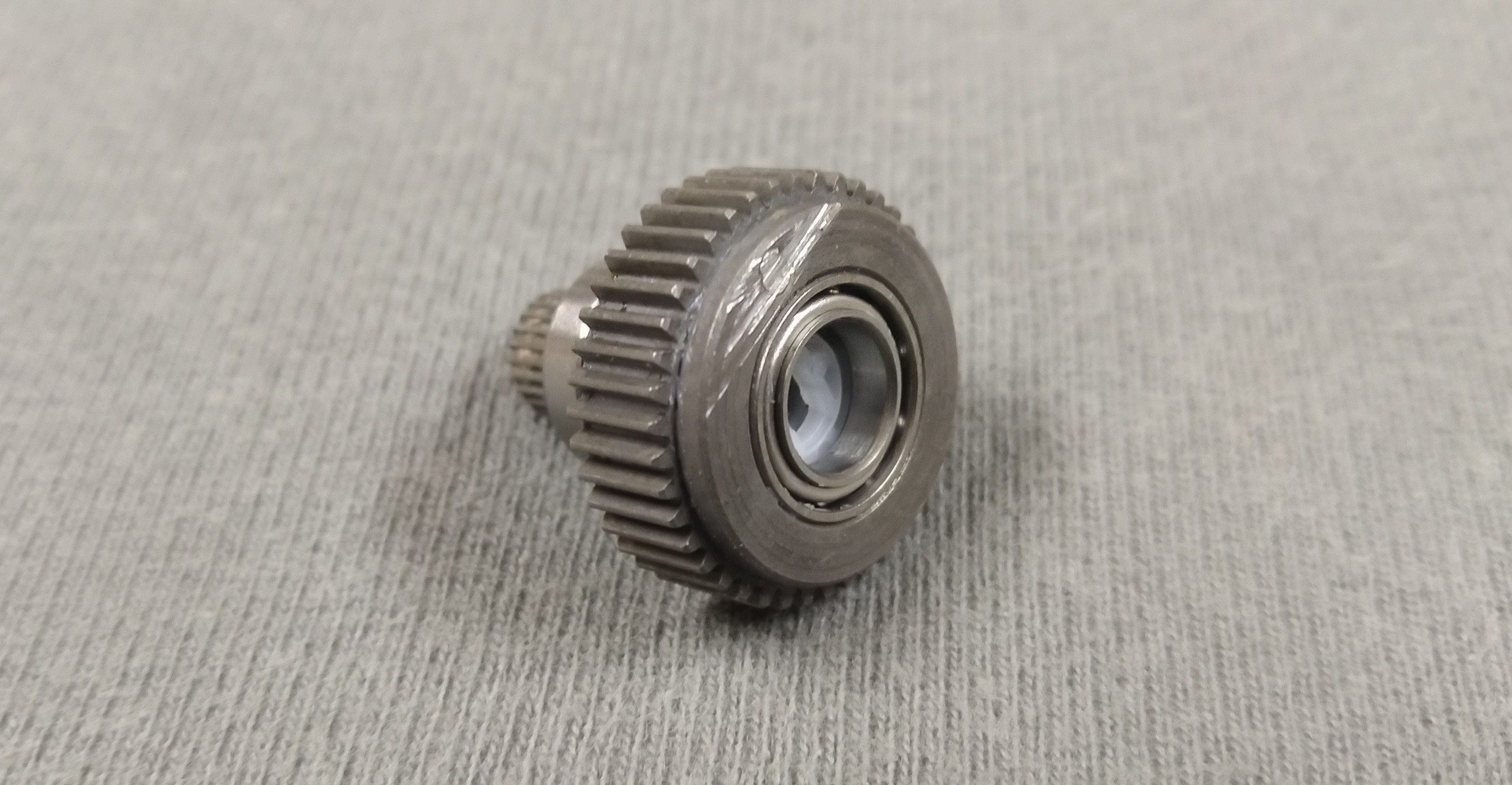
About now I notice that one of the ball bearings doesn’t run as smooth as expected. Rolling the output shaft across an even surface reveals the likely cause. It is slightly bent. Oh well, no refunds at this stage so it will just have to do for a prototype.
PCB modification
Besides the BLDC motor and gearbox the hobby servo also comes with
the necessary electronics to drive it, so why not reuse the
electronics as well? The central part of the servos electronics is a
PIC33FJ32MC202 digital signal controller. To the left of the image
are the MOSFETS and associated driver circuits. The row of five
header pins at the top connects to the small daughter board that
handles the signals from the hall sensors used for commutation.
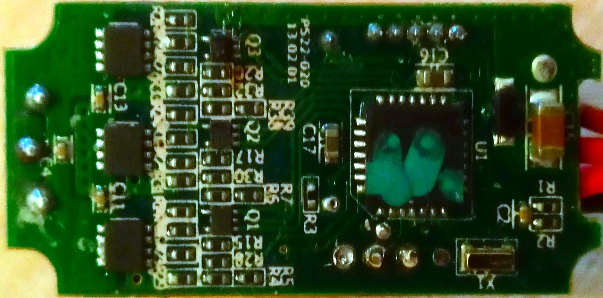
Learning to work with a new microcontroller is outside of this projects scope so I decide to remove the QFN packaged device and hook into the IO signals. With a little probing while the microcontroller is still in place I manage to figure out the signals.
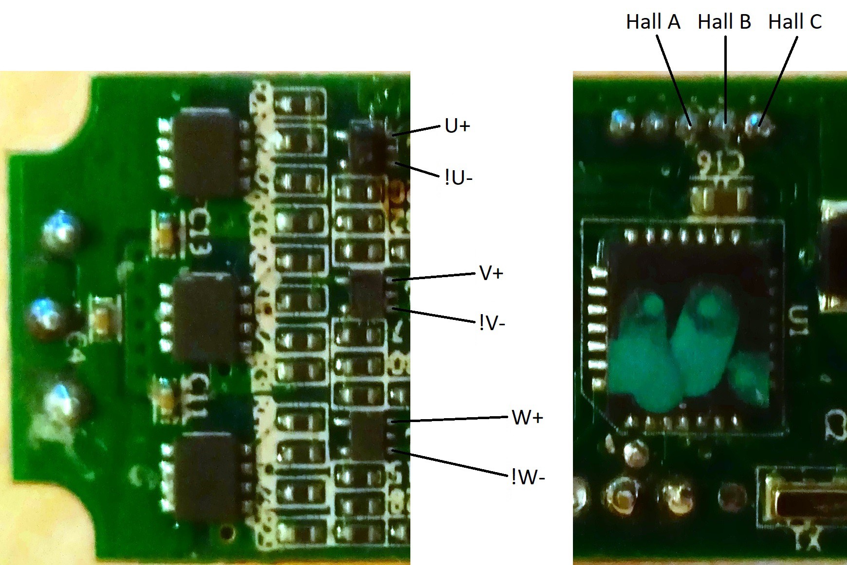
With some hot air the QFN package is easy enough to remove. I use enamelled copper wire to connect to the IO signals and the potentiometers 3V pad. Thin heat shrink tubing works to keep the wires together. I recommend applying a bit of tape over the solder joints for some basic strain relief.
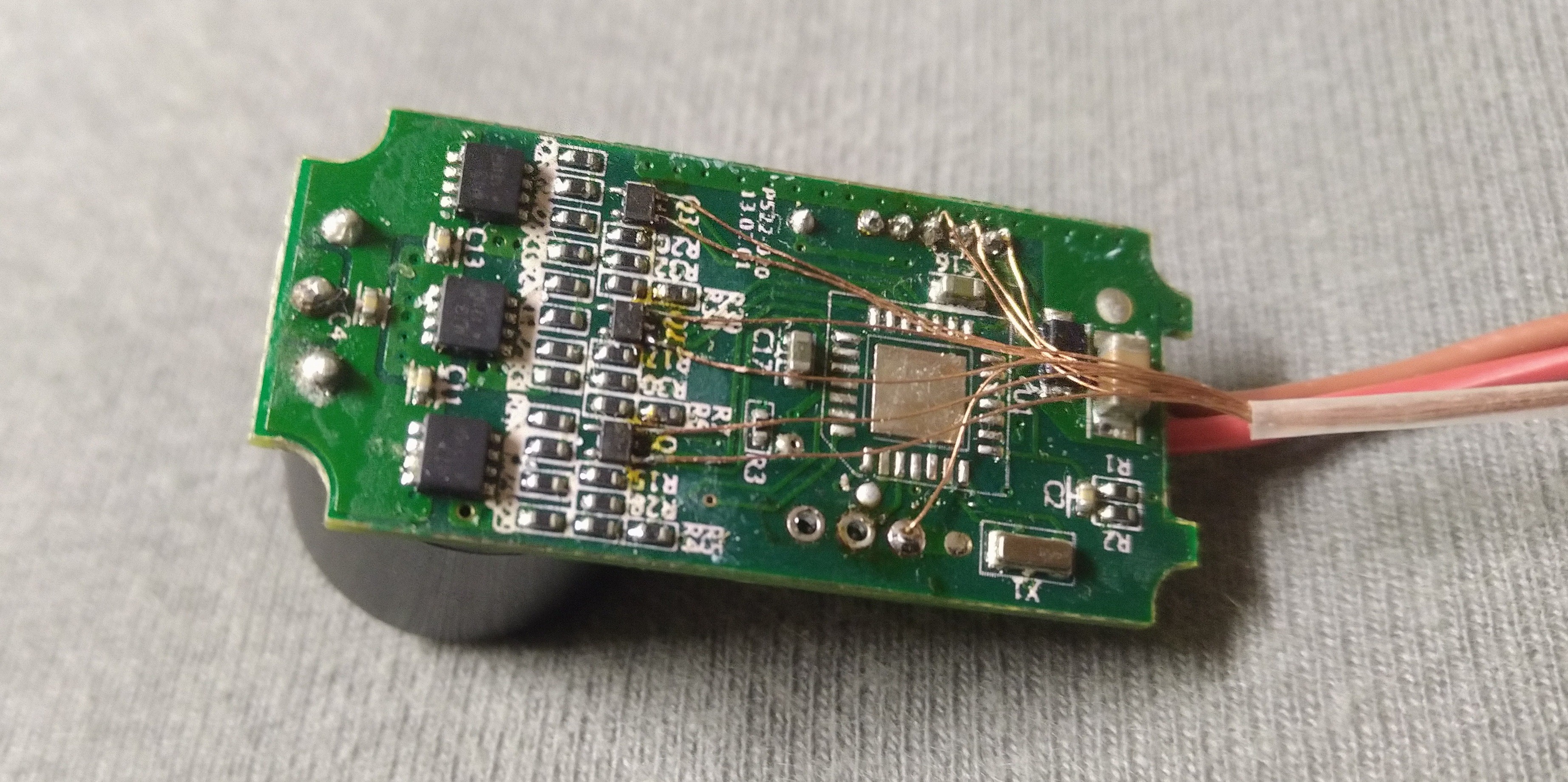
A simple connector is fashioned from a row of pin headers and some tape. By poking the pins trough the tape and then folding the tape around onto itself a nice handle is formed that keeps strain off the copper strands.
Here is the pinout I decided on:
- 3V_out
- Hall_C
- Hall_B
- Hall_A
- U+
- !U-
- V+
- !V-
- W+
- !W-
The servos usual signal input wire is no longer needed. Removing it frees up enough space to get the new wires outside the housing besides the two power leads.
BLDC motor commutation
So how do you make a sensored BLDC motor run? Here are links to some nice appnotes on the subject:
Please be aware that the commutation tables in those appnotes do not apply universally though. The pahse shift of the hall signals can be 60 or 120 degrees and some of your signals might be inverted. In my case all the low side drivers take inverted signals. I have even come across really fancy motors with analog hall sensors. Great if you want high precision control, not so good if you are working with very limited hardware.
Here is the commutation sequence I came up with for my particular motor.
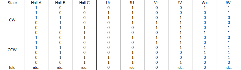
In order to make the motor run clockwise or
counterclockwise, all I have to do is set
the six outputs according to the three inputs. To turn
off the motor, just turning off all high
side drivers works. An electric brake could
be implemented by turning on all low side drivers while in idle. I
don’t need that functionality in this project though.
I measured the motors rpm with a scope probe on one of the hall sensor outputs and it can reach almost 52000rpm. With six commutation steps per rotation that is 5.2kHz. In order to cleanly commutate the motor a considerably higher update frequency is needed. I could setup a timer interrupt to read the hall sensors and get the correct outputs from a lookup table and I later will end up using a timer interrupt in order to get position information from the hall sensors. However there is another, much more fun way to implement the commutation table and you don’t even need a microcontroller for this, Hardware!
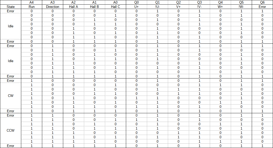
So
there are three inputs and six outputs, well lets add two more inputs
for “run” and “direction” and one more output for “error”.
The state off all outputs solely depends on the state of the five
inputs. That’s combinational logic. No
need to bring out the Karnaugh maps and logic ICs though. A truth
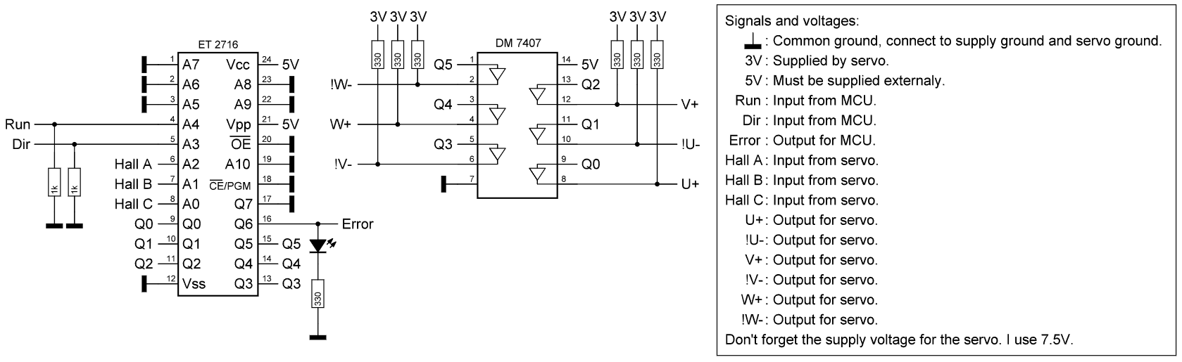
table can easily be realized in memory. In this case the ET/D
2716,
a 2048 x 8 EPROM with parallel addressing. It runs on a single 5v
supply and needs no clock, it simply spits out its 8 data bits
depending on the state of the 11 address bits. I have a couple of
those left over from an Apple II clone my
dad was building. I
never saw the rest of the machine.
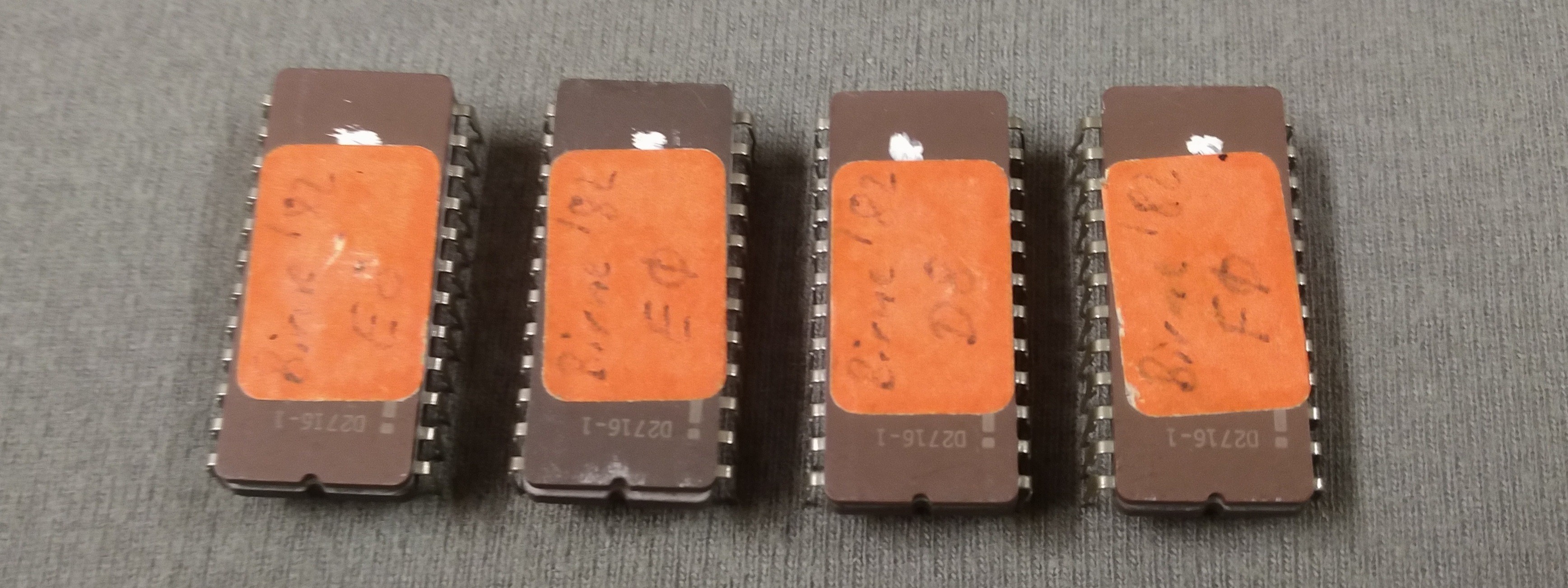
I extended the truth table with the new in and outputs and ordered it by the input bits. The whole thing gets written onto the EPROM.
My hobby servo works with 3V signal levels. For the hall signals that’s no problem, the EPROM takes anything above 2V as a high level. On the outputs I decided to roll it save and put in a DM 7401 buffer with open collector outputs. I use pull up resistors fed from the servos own 3V to get to the right voltage. Here’s the schematic.
The motor can now be run from two digital outputs
just like a brushed motor hooked up to
one of the driver ICs we all are so
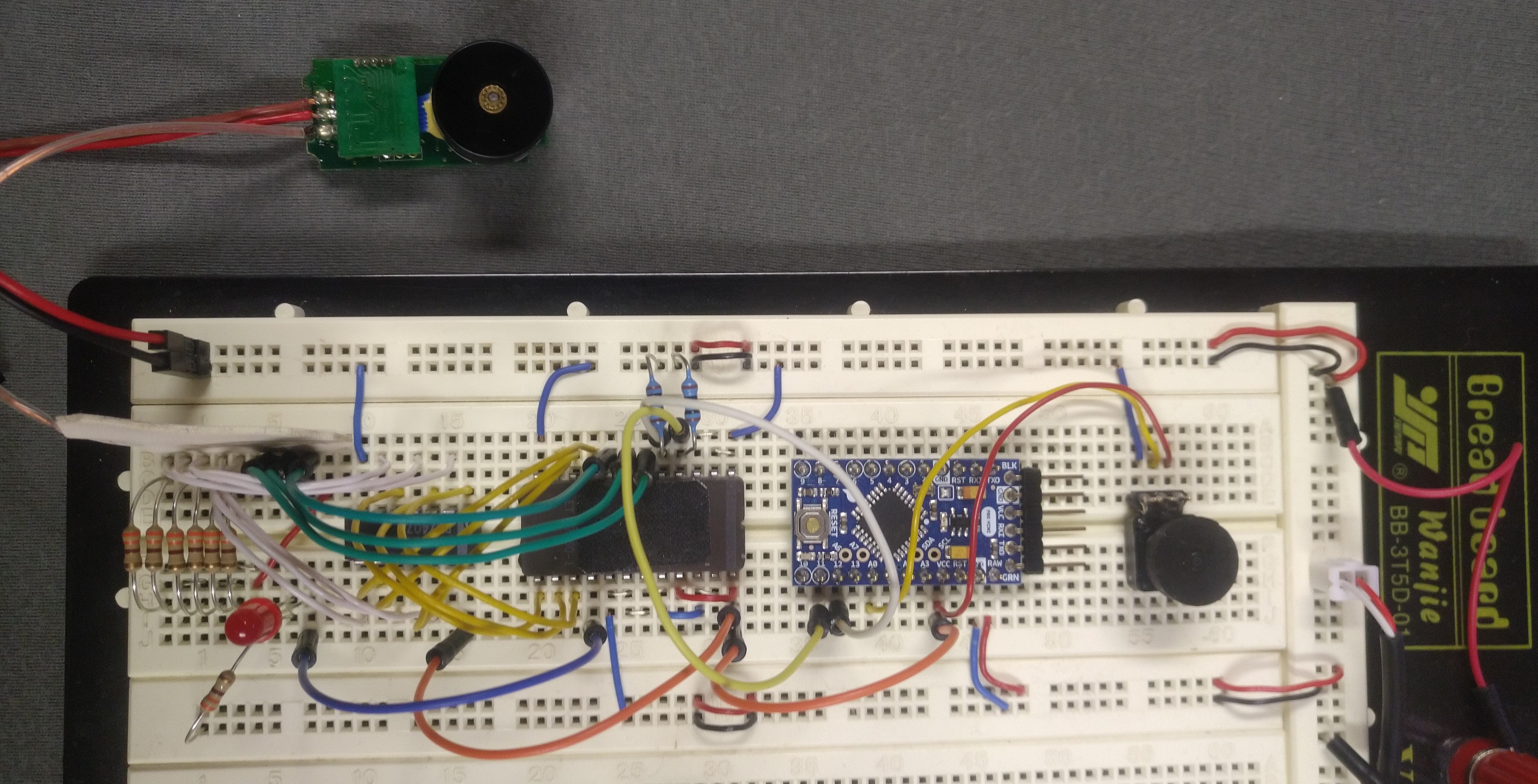
familiar with. I built a
test setup on a breadboard featuring a
potentiometer to
set the PWM duty cycle. A short video of a test with this setup is included in the project files.
The rest of the circuit
In order to get the same control over the amount
of pushed filament as with a stepper, closed loop position control is
needed. This can be achieved with a microcontroller.
I’m using a clone of the arduino pro nano
board I had around. Most arduino boards should work for this project,
in fact most other microcontrollers
would probably work as well, the requirements are not that high.
We need:
- 5 digital inputs. One of them interrupt capable.
- 2 digital outputs. One of them PWM capable.
- A timer interrupt at or above 6kHz.
Have an overview of the entire system:
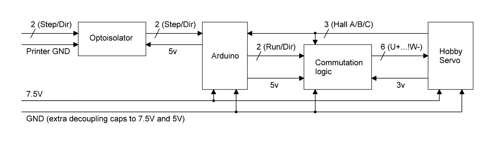
I didn’t bother to hook up the error
output and just left the LED as a visual indicator. The
step and direction signals come from the
3D-printer, usually they go to a stepper driver. I chose
to use optocouplers
on those two inputs and keep my circuits ground separated from the
printers ground just to be save, there is enough other stuff that can
go wrong.
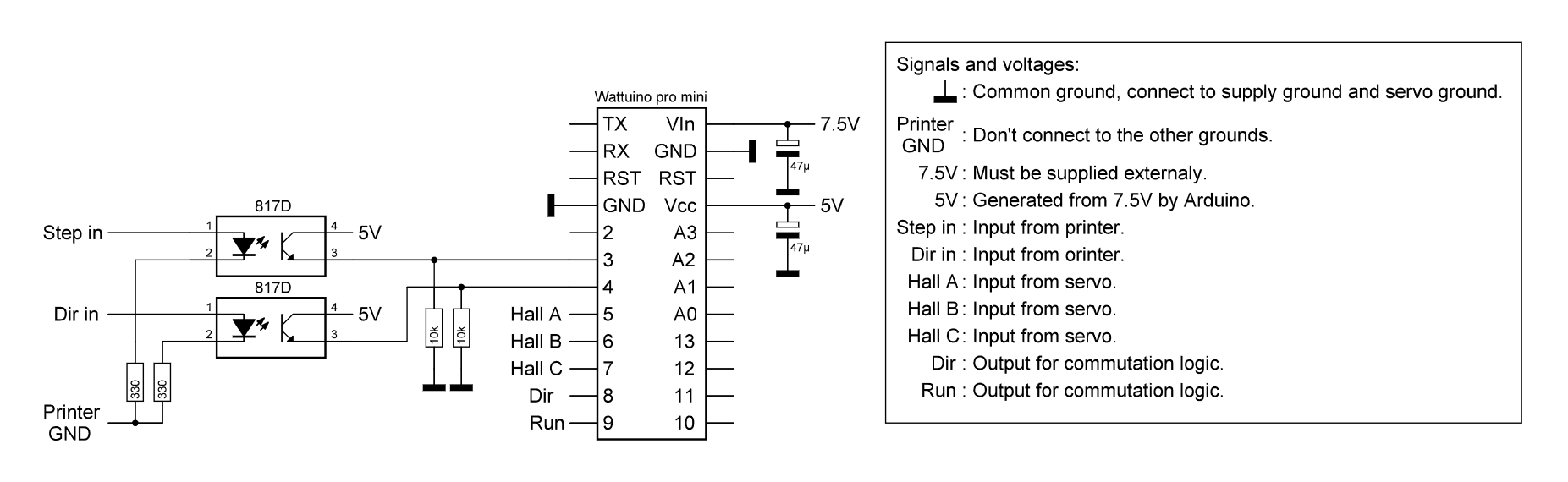
Decoupling capacitors were deemed necessary after experiencing some erratic behavior. 47uF seems to do the trick.
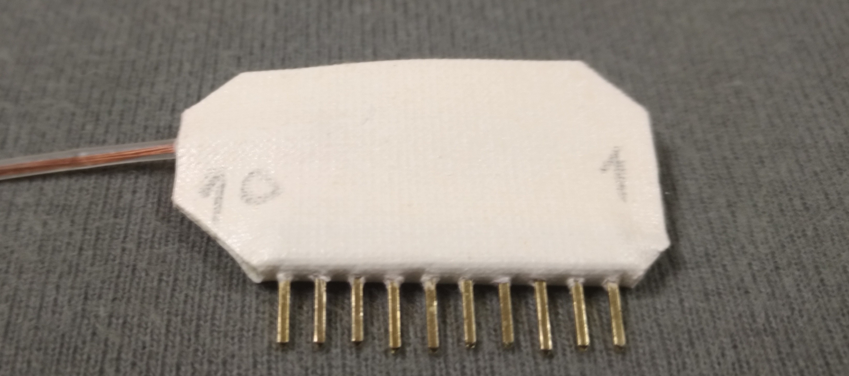
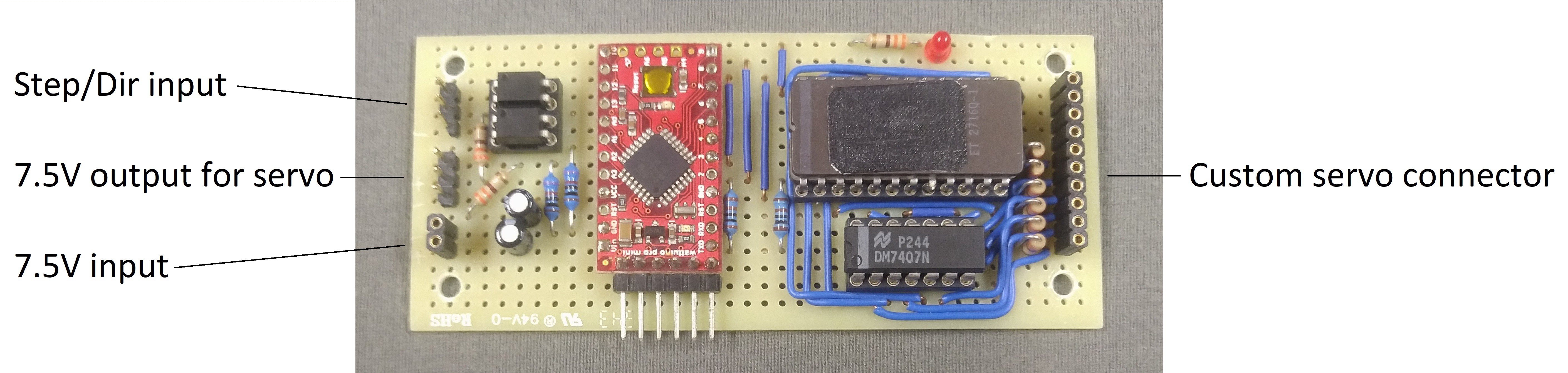
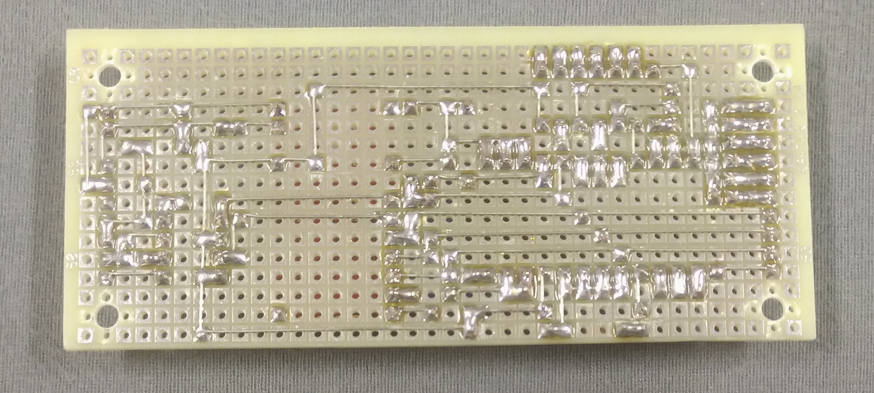
Here is
the entire circuit soldered onto perfboard. For labeling I usually
just scratch the most important designations into the front of the
board, I’ve found this to last longer than marker or printed
labels.
Filament drive hardware
For the filament dirve I came up with a flexure design. Since there is no space for an adjustment screw, the pressure on the filament can only be adjusted with a shim between the main block and the spring. A thickness of 1mm for the shim worked well for me. Please excuse the use of uncommon parts as this was mostly built from whatever I found in my parts bin.
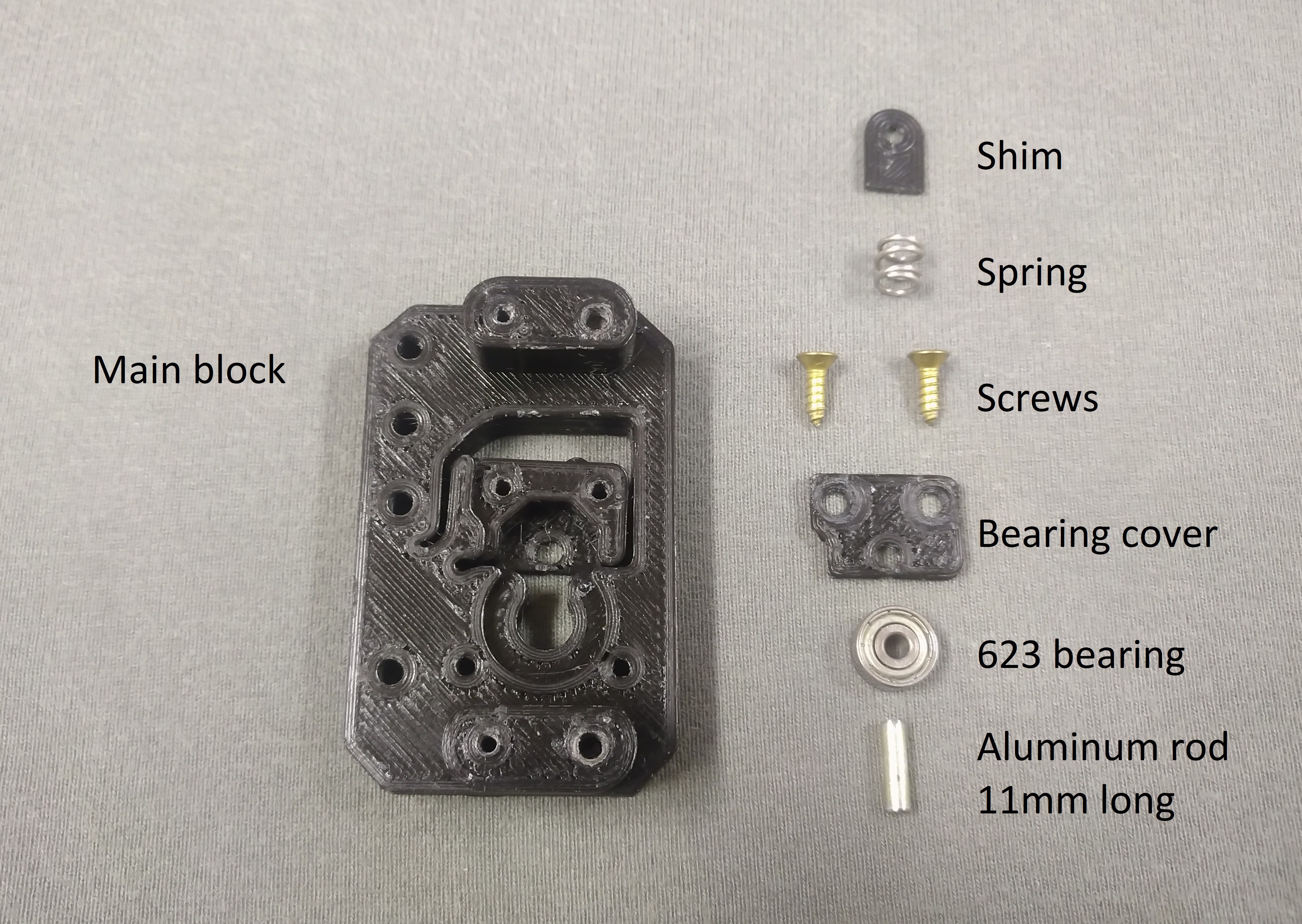
I’ll do my best to characterize the components.
- The spring has a free length of 6mm, an o.d. of 6.2mm, an I.d. of 4.5mm and a pitch of about 2.8mm.
- The screws are 9.6mm long which makes them poke out of the plastic a little. The o.d. of the screws threads is 2.8mm, the solid I.d. is 2.1mm. The head has an o.d. of 5.4mm.
- For the bearing I use a 623-ZZ. Any 623 bearing will probably do for this job.
I’ll include STL files for the printed parts in this projects files.
Once it is assembled the filament drive looks like this. The mangled screw holes originate from a later mounting attempt.
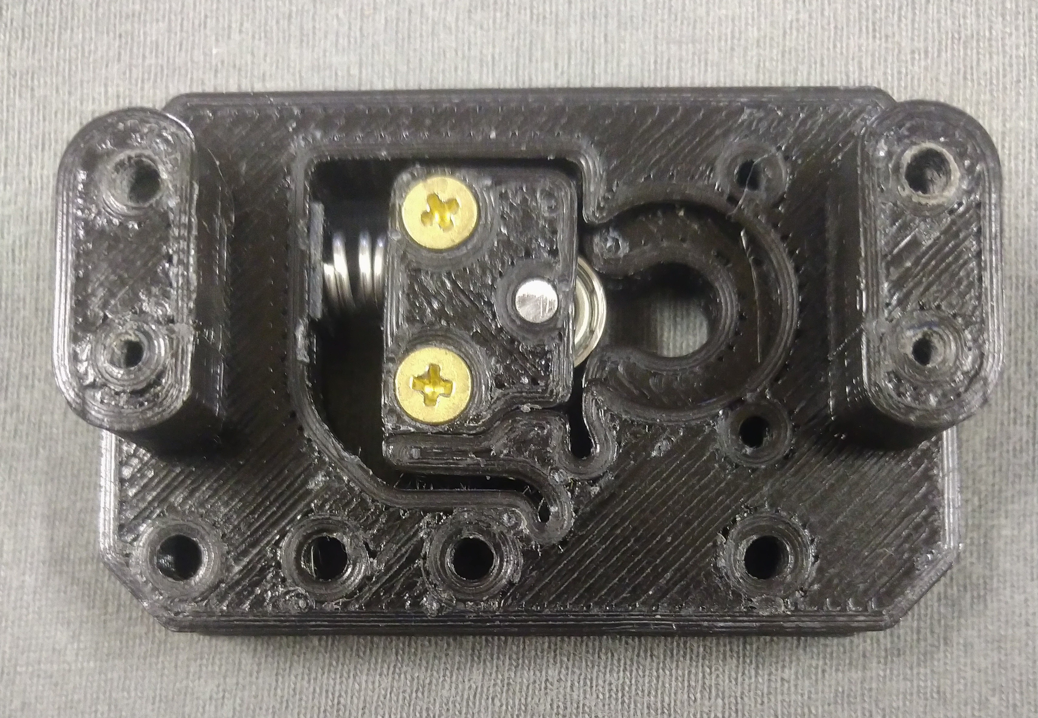
The modified hobby servo mounts onto the two raised sections. Two printed washers not visible in the picture replace the rubber grommets originally supplied with the servo.
Software
The Arduino program for this project comes in at at just under 200 lines including whitespace. I setup a timer interrupt at 8kHz in order to sample the three hall sensor inputs fast enough so there is no realistic chance of missing steps. A rising edge interrupt attaches to pin 3 for the step signal input. I read the port registers directly instead of using digitalRead() this allows me to read multiple inputs at once and save some valuable interrupt time.
For the PID control I went with the default PID_v1 library. For the first tuning pass I ran the bare motor with no gear train. Once I had working parameters for the bare motor I put the gears back in place and re-tuned using the original parameters as a starting point. The PID parameters I ended up with are Kp=20, Ki=0.01 and Kd=0.07.
One worry I had was that the values for the target position and current position might overflow on large prints. So instead of using absolute positions I went with Step/Dir inputs and encoder steps since the last iteration and looped the last iterations deviation back as well. This way no value will ever grow very large. Below you see my attempt at visualizing the control loop I built.
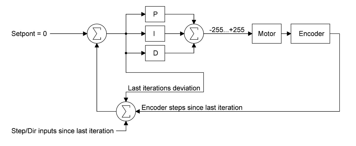
I’ll include the programs latest version in this projects files as sketch_servoextruder.ino.
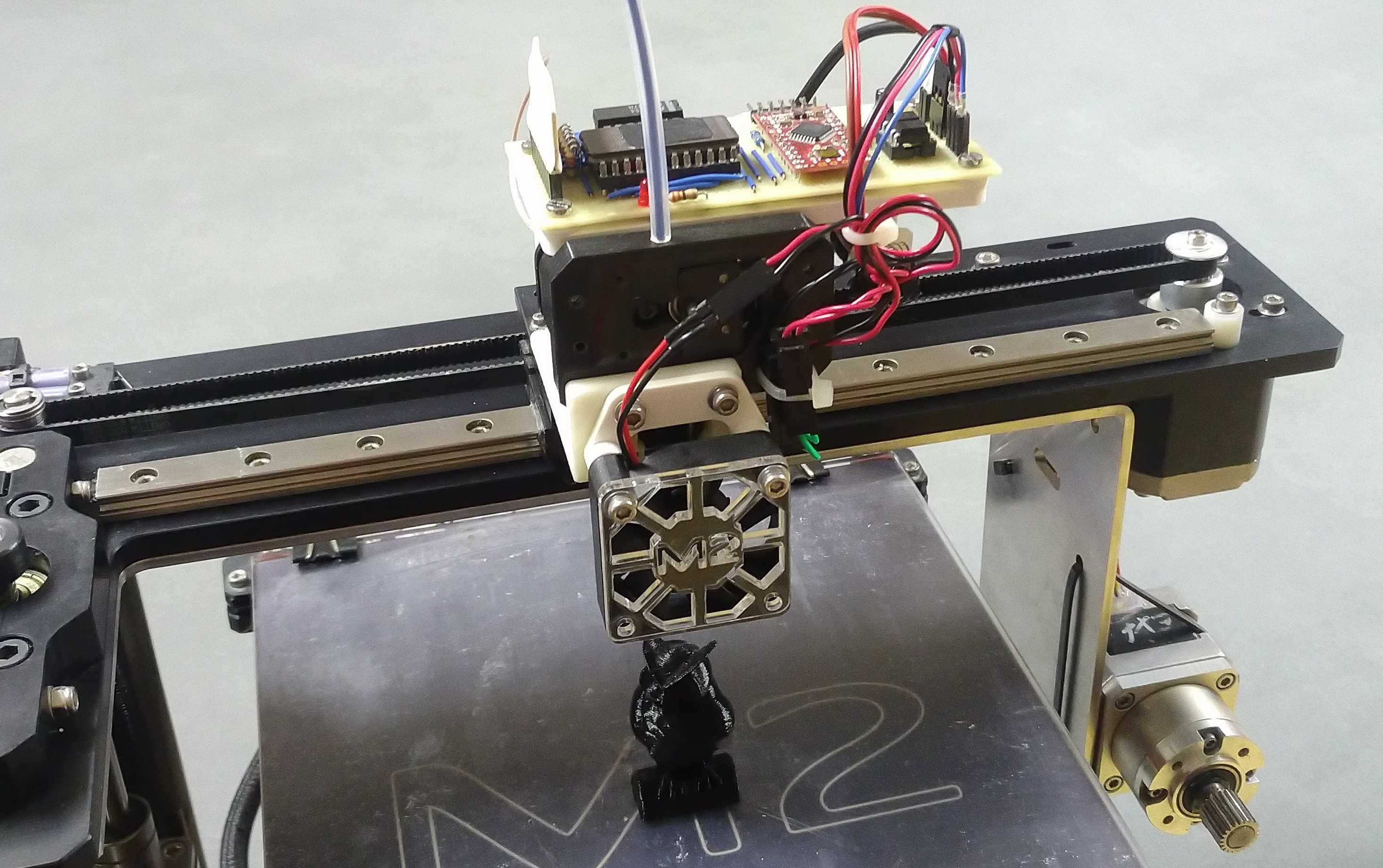
Printing
I mounted the filament drive and circuit board onto the X-carriage of my printer. The original extruder motor is still attached, you can see it zip-tied to the frame in the bottom right of the picture. The step and direction signals and a ground wire are branched from the E-driver and routed up to the optocouplers on the perfboard. The filament drive is powered from its own 7.5V supply.
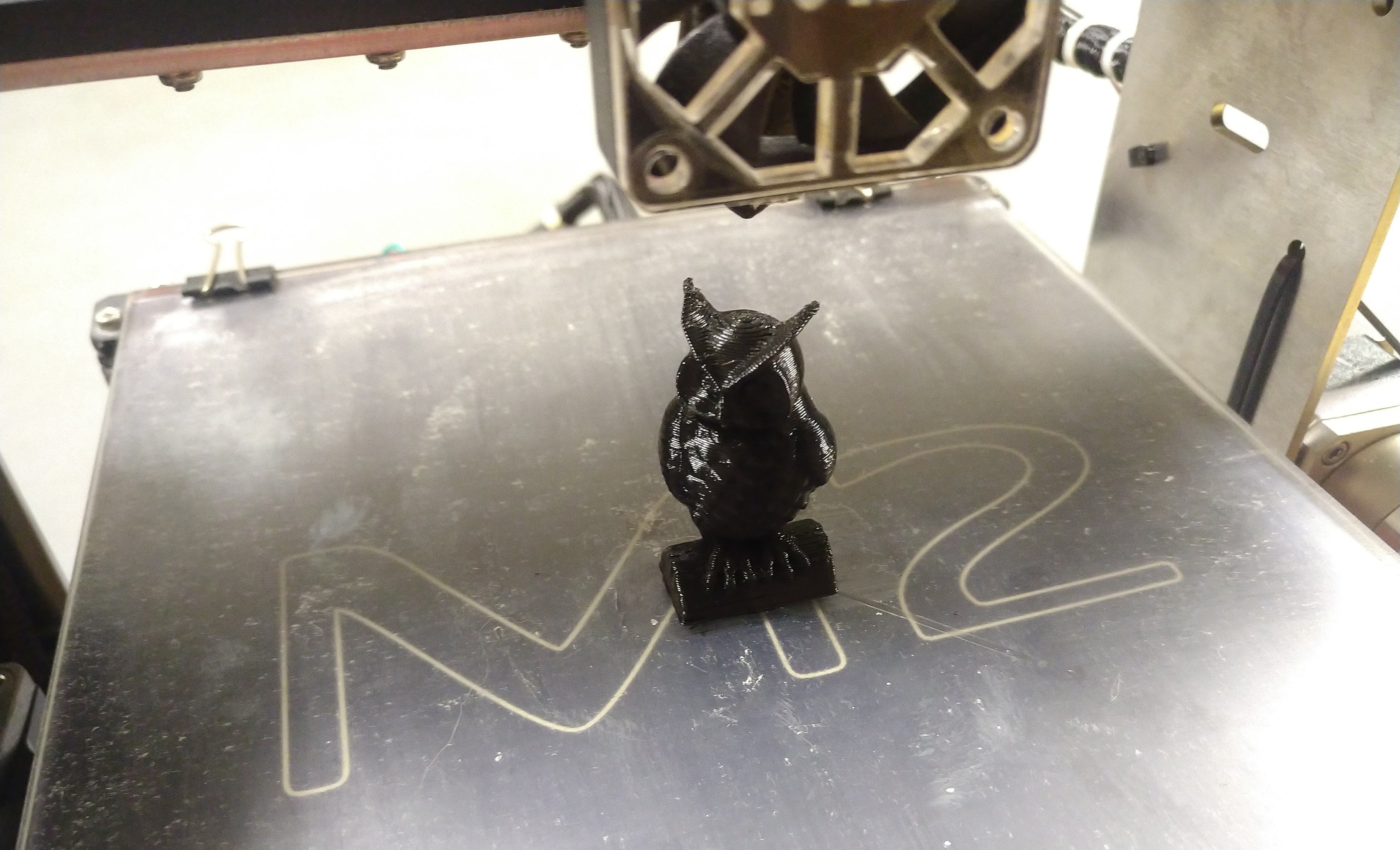
The only thing left to get printing is setting the correct stepps/mm in the printers firmware. I ended up with a value of 126. After applying a new z-offset for the newly mounted hotend I set out to print a small owl statue. I threw a short clip of the extruder in action into this pojects files. The print came out nicely except for some curling due to the arguably bad cooling setup.
This project is considered a success and will be shelved until I get
around to actually using it on a printer that can properly benefit
from such a lightweight solution. In the meantime I hope this
documentation is of use for anyone wanting to build something
similar.