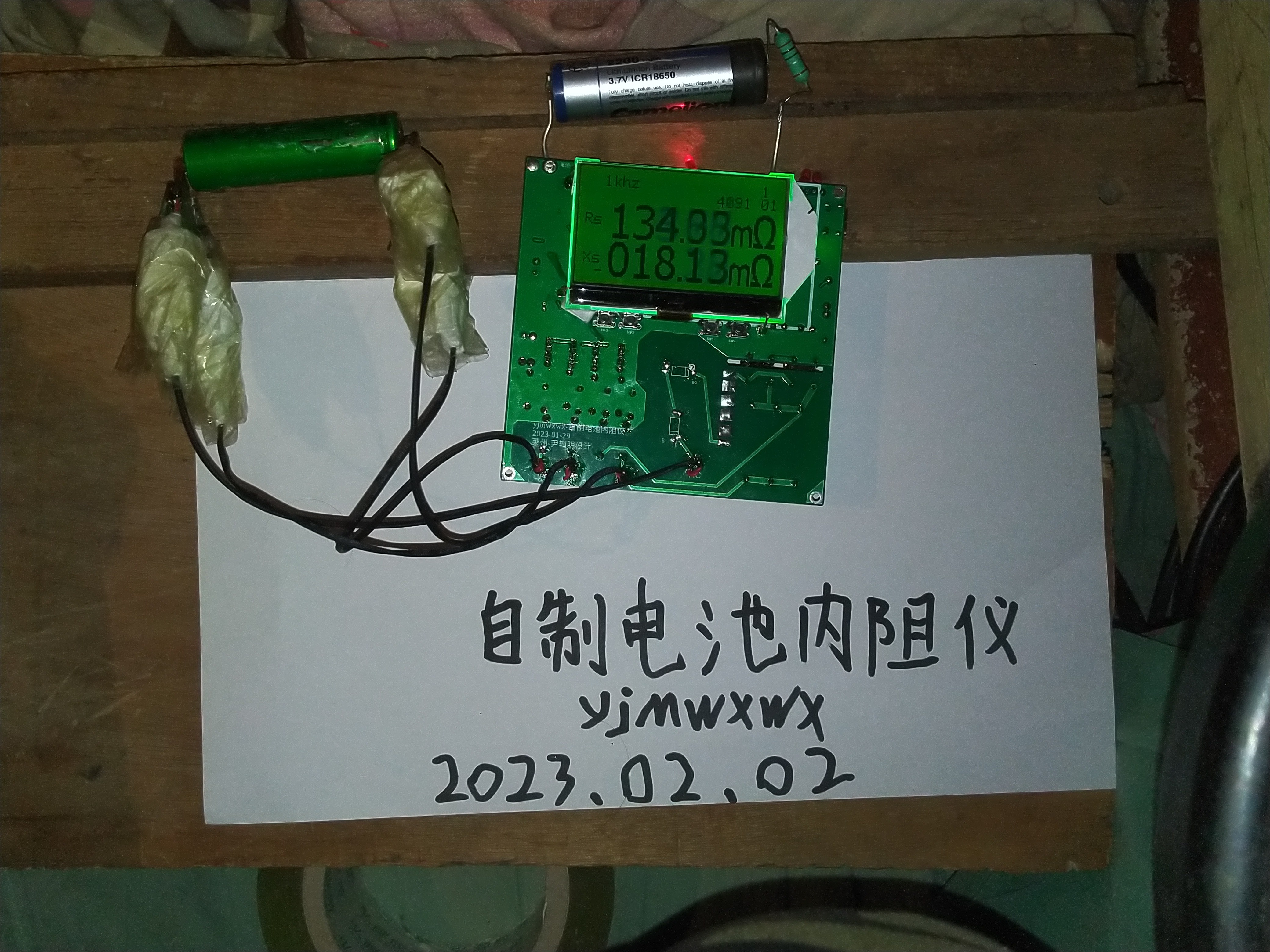
yjmwxwx
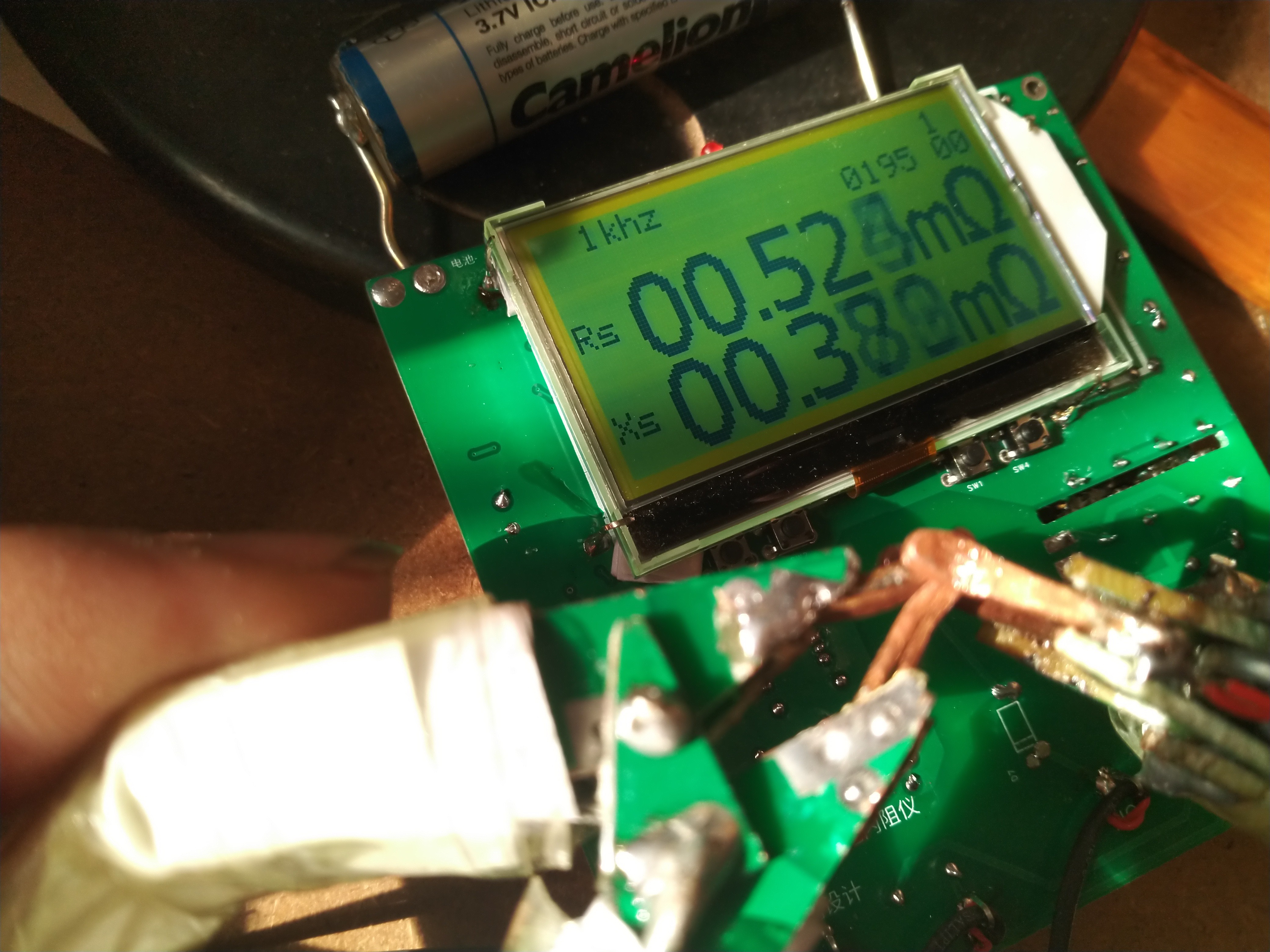
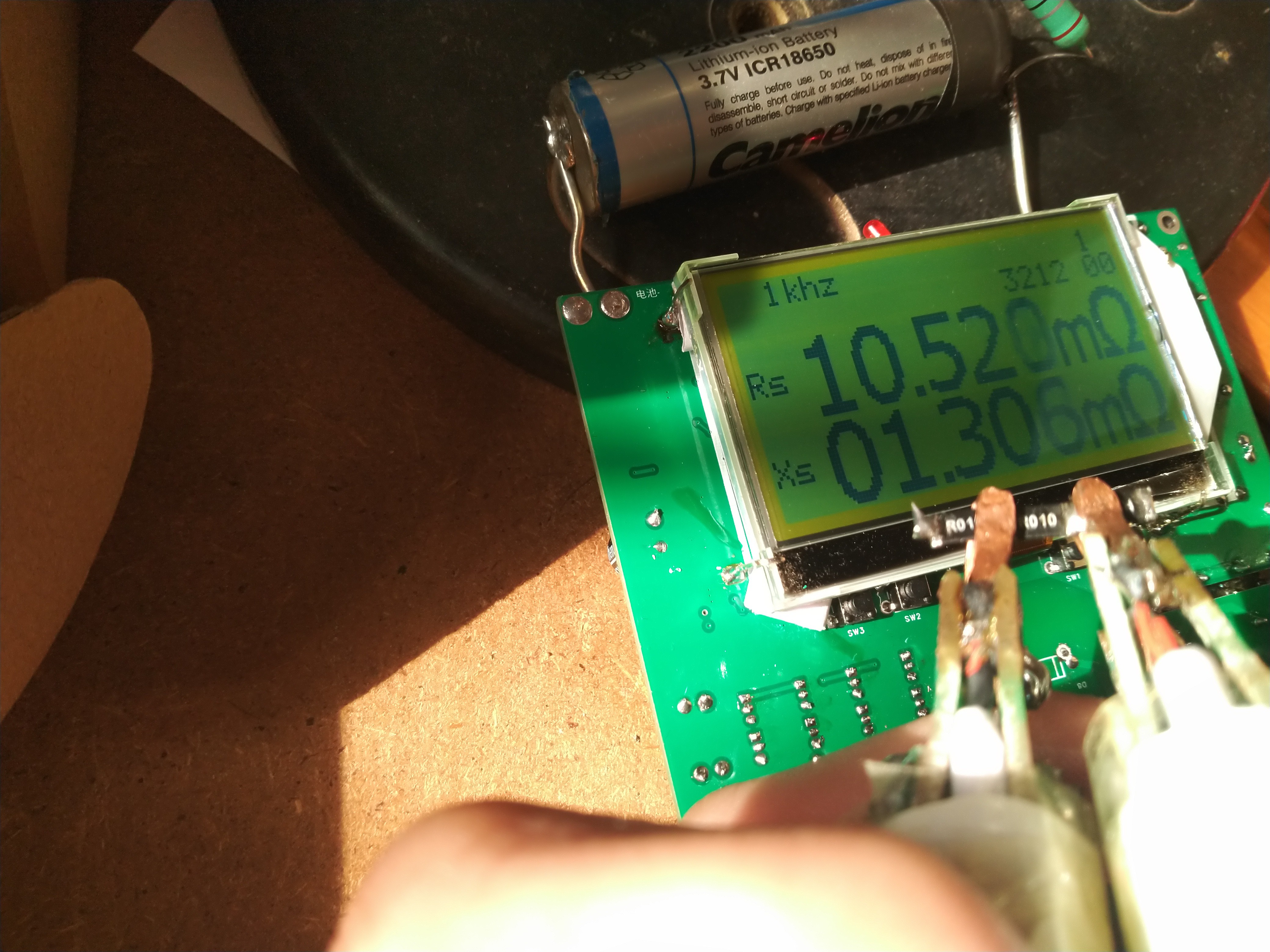
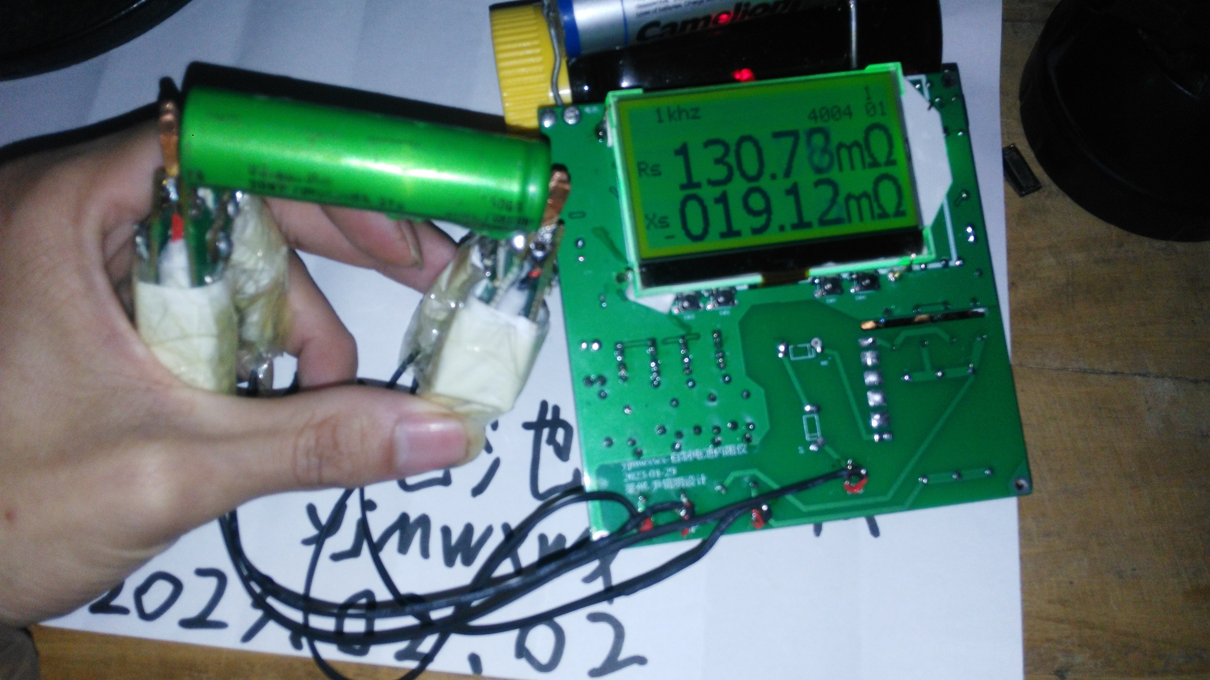
There are several 18650 batteries in the hands do not know good or bad so idle homemade a battery internal resistance meter, but I can not do the technical measurement is not allowed, only a sloppy measurement of the approximate. The range of 1 milliohm to 3 kilo-ohm, the balance point is 3 ohms deviation from the more inaccurate, calibration procedures I do not know how to write.
But there are still some advantages, that is, the protection circuit is more perfect, can support the measurement of hundreds of volts of the battery, but the capacitor did not discharge resistance, measurement of high-voltage battery to pay attention to discharge.
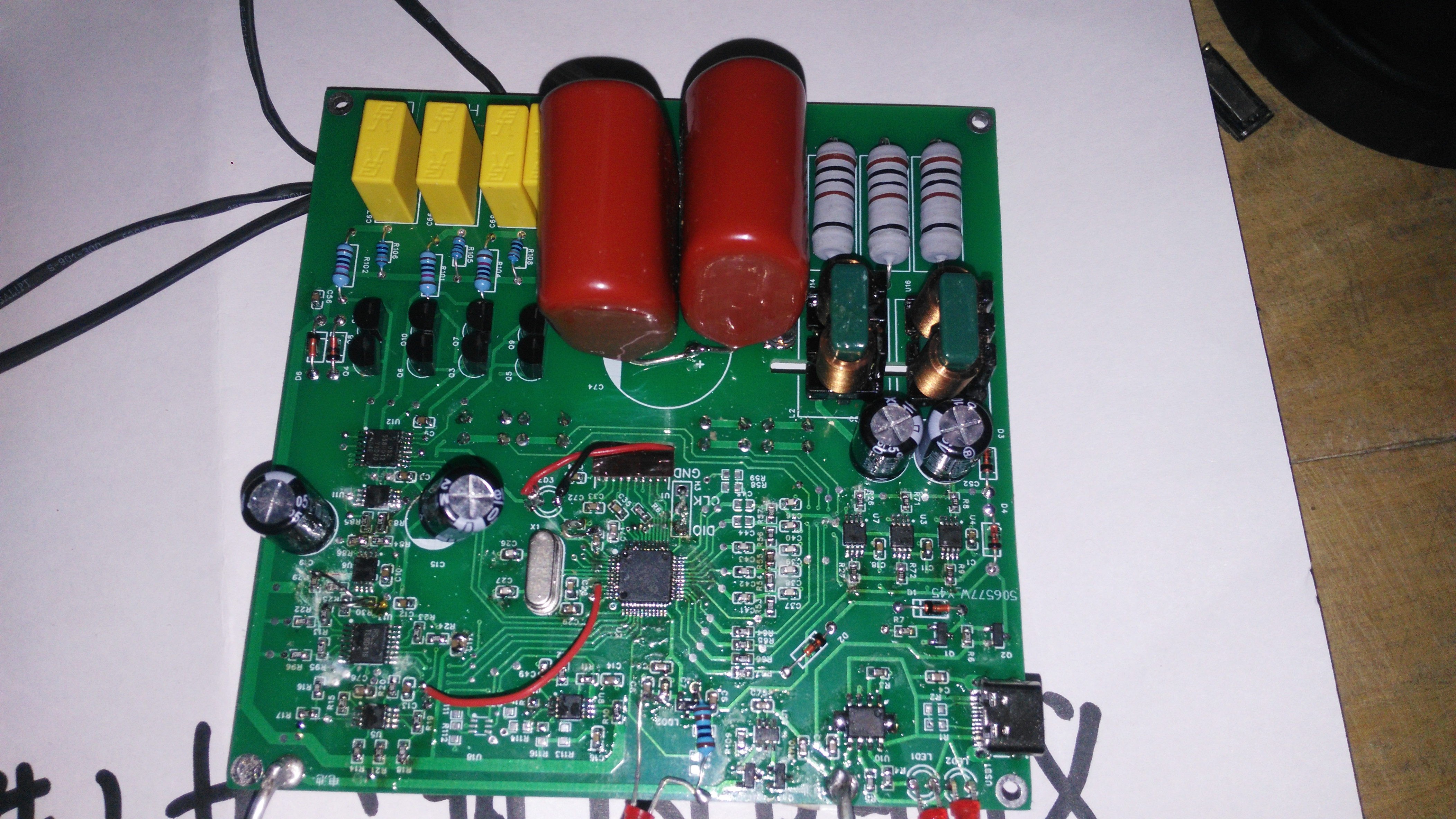
In addition to the ST7567 COG12864 liquid crystal, other components are purchased from China LCSC
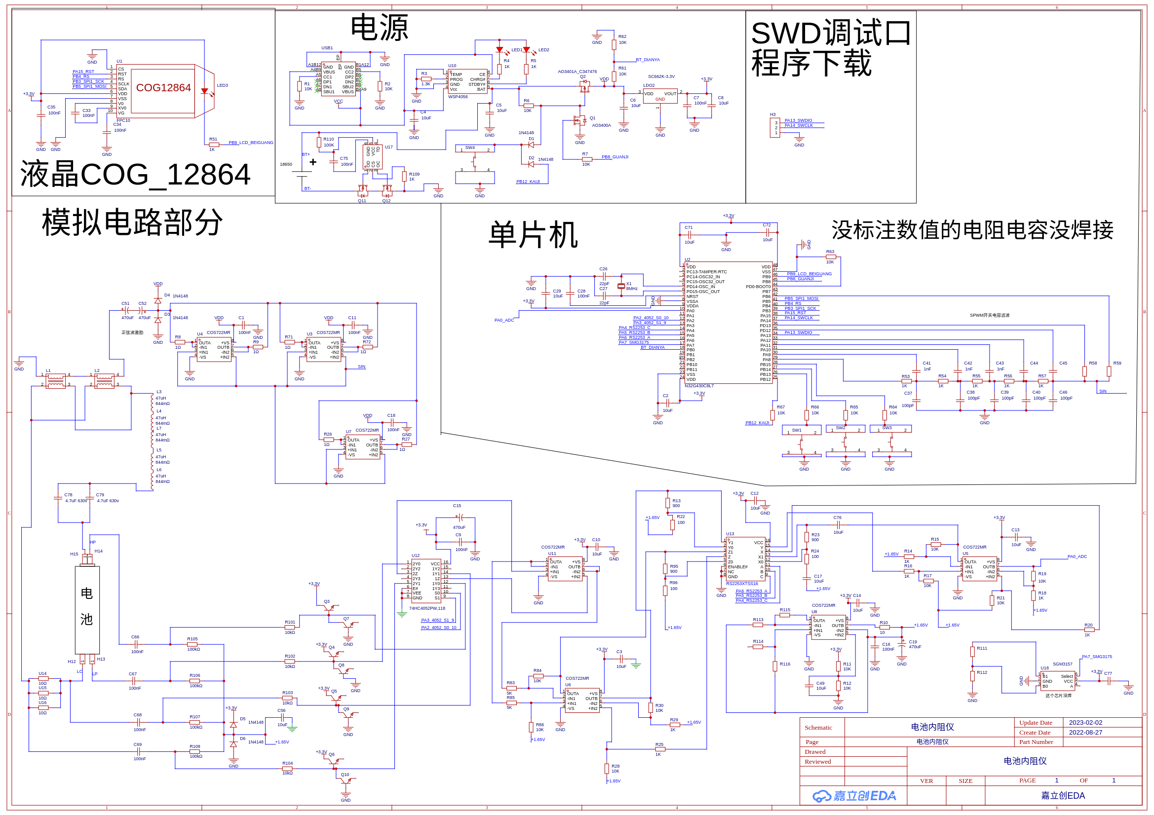
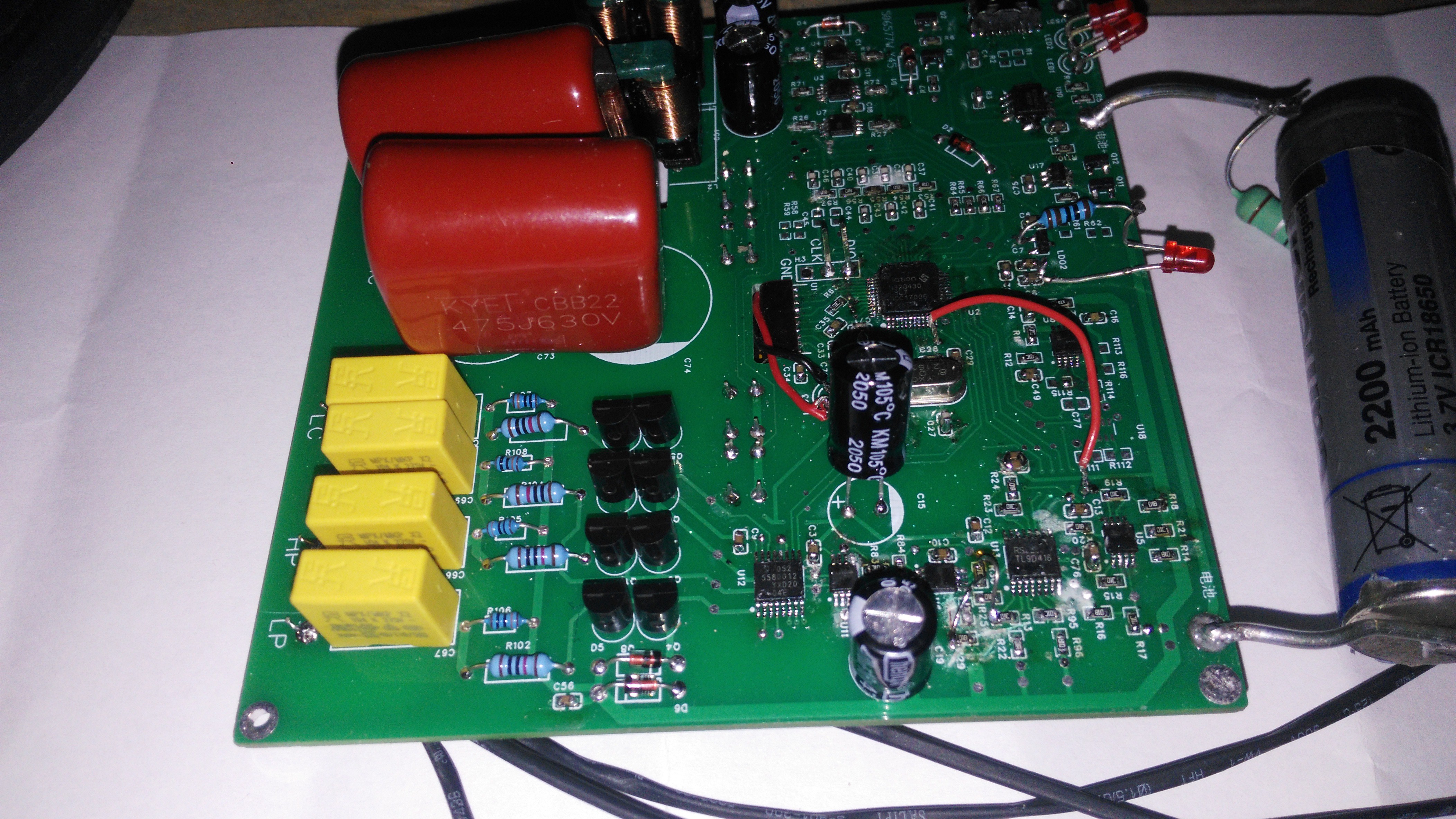
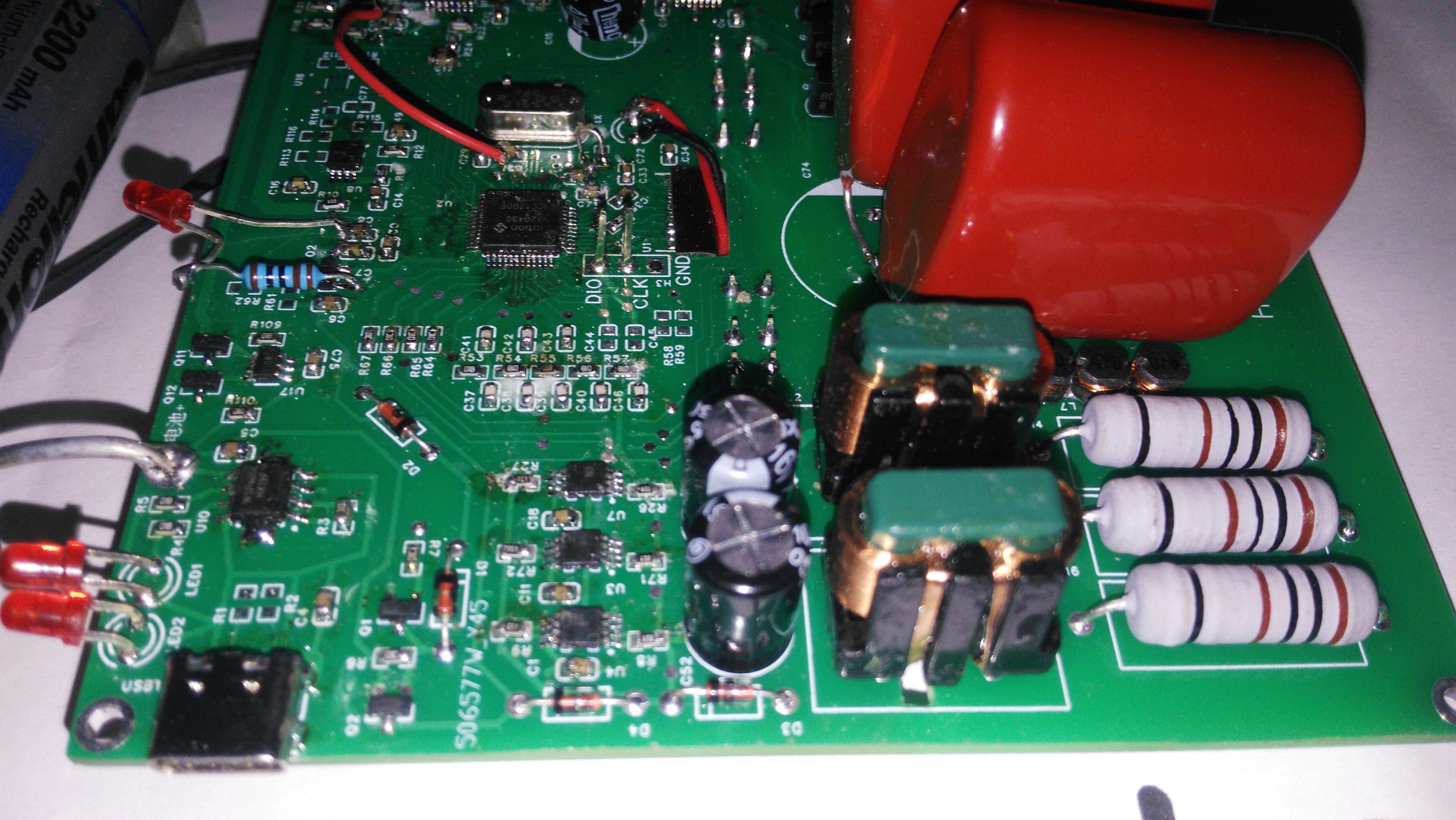
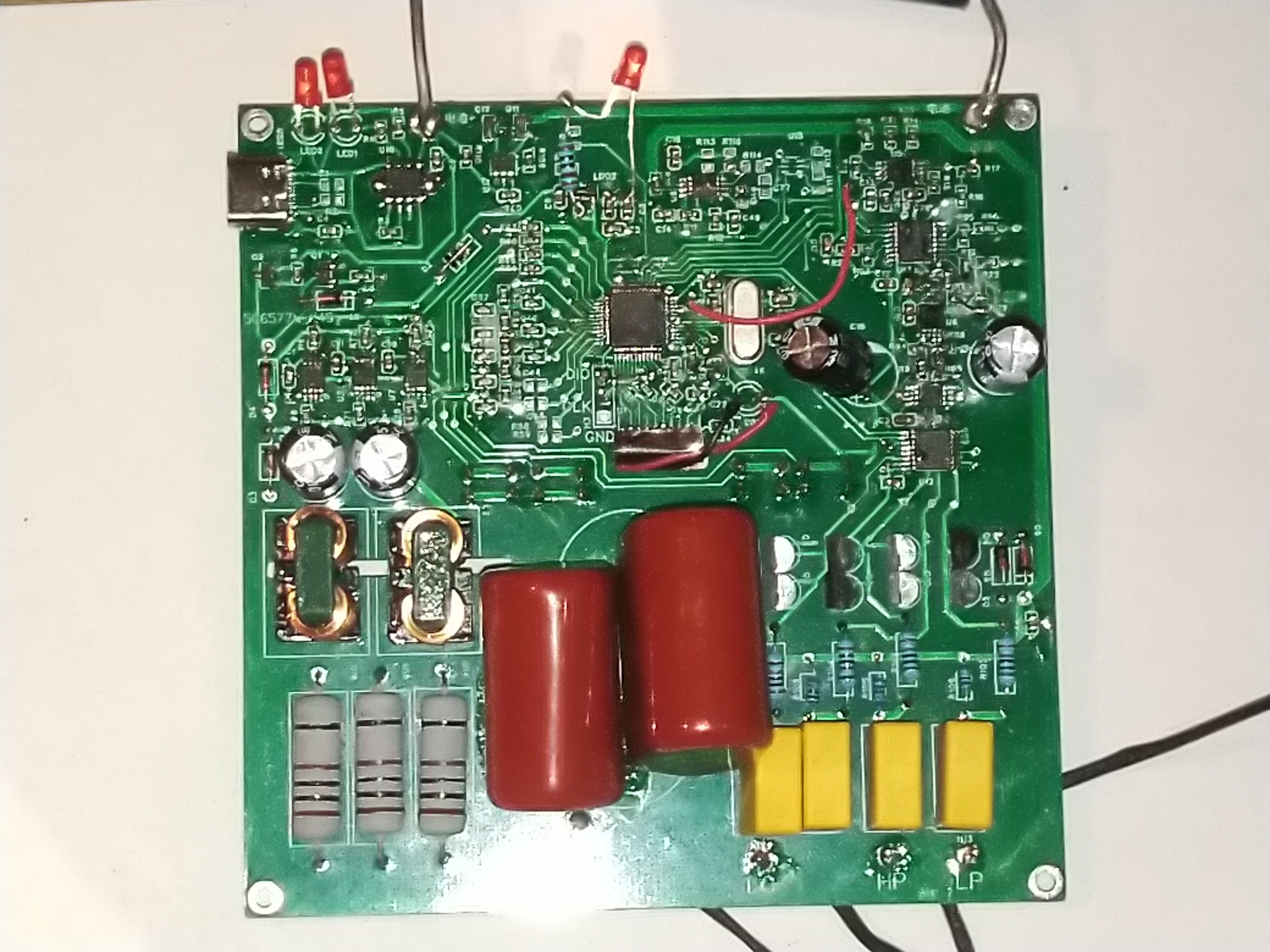
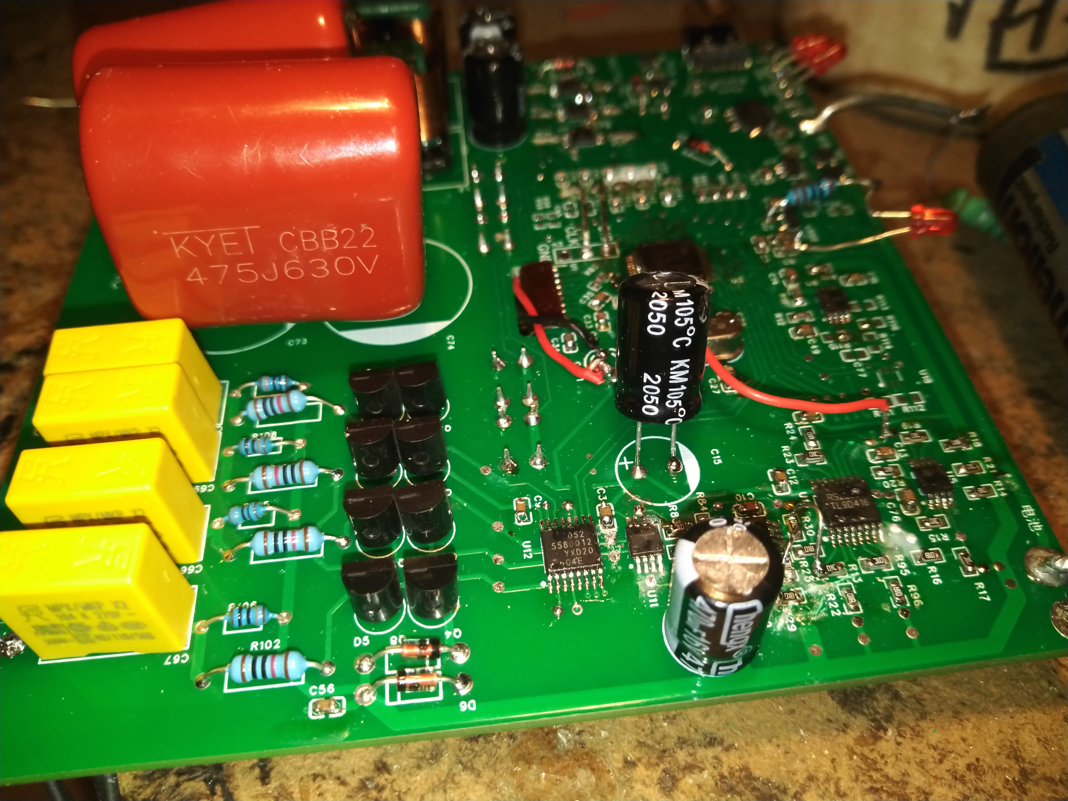
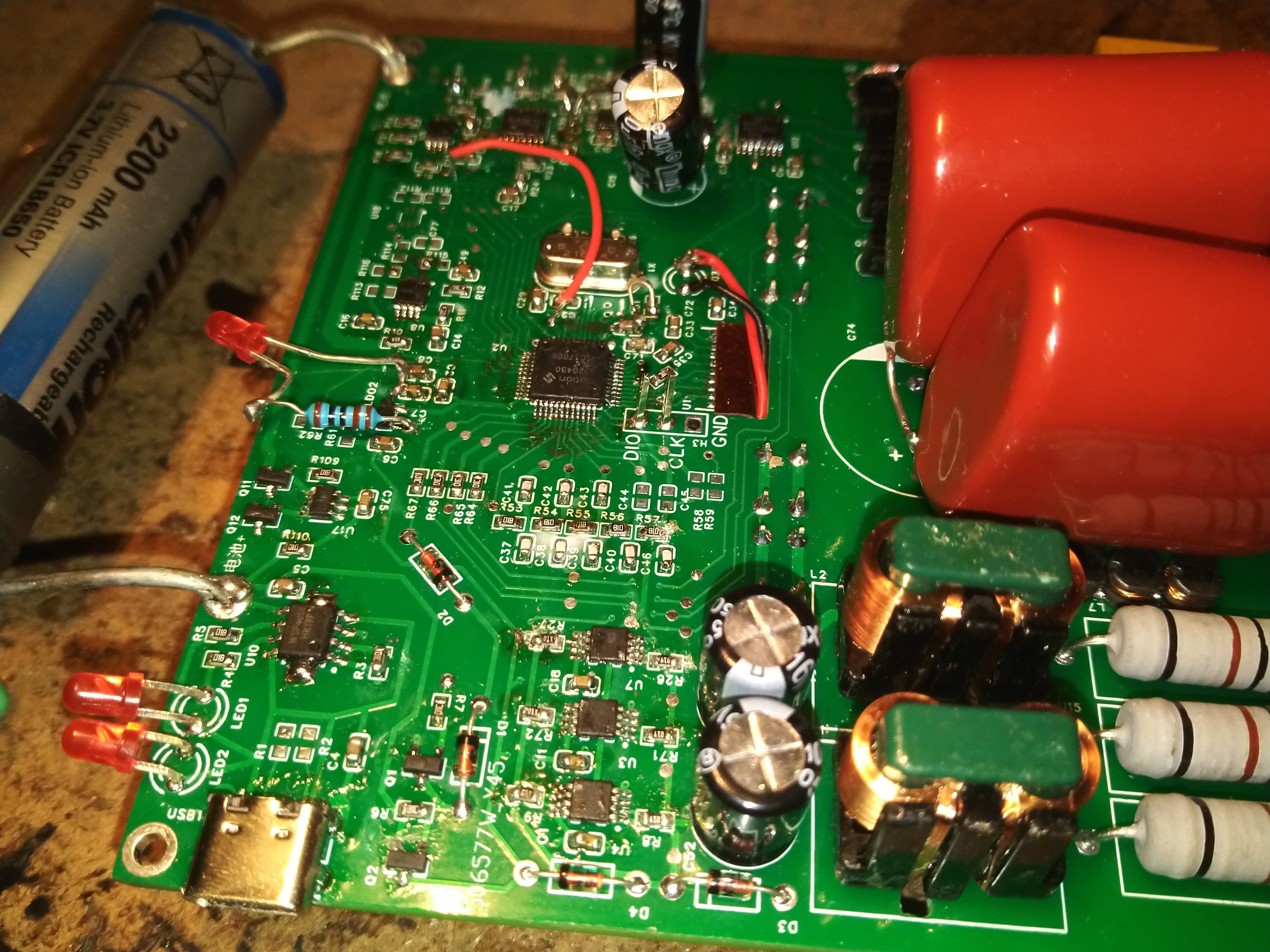
Principle: the microcontroller output all the way SPWM, after RC filtering into 1KHZ sine wave, into six parallel op-amp amplification, why parallel? Because I will not do triode amplifier circuit. The back of the op-amp connected to the transformer (green magnetic ring common mode inductor 10mH each, DC resistance of 200 milliohms), the other end of the transformer is connected in parallel with three 10-ohm wirewound resistors as current sampling resistors and batteries in series, two CBB 4.7uF 630V capacitors in parallel to do straight capacitance, through the 74HC4052 analog switch between the sampling resistors and batteries to collect a cycle on the switch, the collected The voltage to enter the back 1x, 10x, 100x, 1000x adjustable amplifier, combined with the amplifier to achieve 3.3 milliohms, 33 milliohms, 333 milliohms, 3.33 ohms, 33.3 ohms, 333 ohms, 3333 ohms several gears. The amplified signal into the microcontroller and 1KHZ COS and SIN table multiplied and accumulated to get the real part of the imaginary part, the voltage on the battery divided by the voltage on the current sampling resistor and then multiplied by the sampling resistor resistance value will come out of the battery internal resistance.
Circuit PCB using China JLCEDA drawing
 ROFLhoff
 Sagar 001
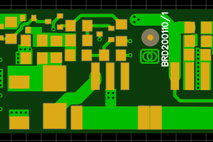
 Christoph Tack