Been plugging away at it, and while the Arduino Mega I decided to use is barely up to the task, it can be hacked to be good enough. Here's some preliminary driver code and the hardware hacks required to get it running.
First the software.
#define CTRLPINS   PORTA            // Port A used for all the control signals
#define CTRLPOUTS  PINA             // Easier and faster to read port state than keep a local variable
#define Data1      PORTC            // Port C is for the RGB data

#define DDCTRLPINS DDRA             // Data direction settings. Change these
#define DDData1    DDRC             // to patch ports above

uint8_t UPDATE;                     // Flag to check if data is ready for update
uint8_t ROW;                        // Keeps track of the row we're updating

void setup() {
  noInterrupts();                   // Disable interrupts while we set things up

  DDCTRLPINS = 0xFF;                // Set data direction to "output" by setting these registers
  DDData1   = 0xFF;

  ROW = 0b00001110;                 // Rows are active LOW so 00001110 = Row 0 active
  UPDATE = 0;                       // Clear UPDATE flag

  // Set up timer/counter. Refer to ATMega datasheet section 17.11.1
  TCCR1A = 0;                       // Reset Timer1 control Register A
  bitClear(TCCR1B, WGM13);          // Set CTC (Clear Timer on Compare) mode
  bitSet(TCCR1B, WGM12);
  bitSet(TCCR1B, CS12);             // Set clock source to T1 (pin 31 of the MCU, NOT Arduino board!)
  bitSet(TCCR1B, CS11);             // This pin is not connected to anything on the Arduino Mega 2560
  bitSet(TCCR1B, CS10);             // So to use it you'll have to solder your own bodge wire

  TCNT1 = 0;                        // Reset Timer1 to known state
  OCR1A = 4096;                     // Set compare value. Interrupt will trigger when counter reaches this value

  bitSet(TIMSK1, OCIE1A);           // Enable Timer1 compare interrupt

  interrupts();                     // Enable interrupts again
}
The above clip is the setup, written in the Arduino IDE so I use some Arduino wrapper functions because speed isn't critical here.
The strategy is to use the 16MHz system clock, divide it by 4 (down to 4MHz) externally and use that for our PWM clock source. We will then feed that 4MHz clock back into the MCU to make a counter go up.
When that counter hits 4096 cycles (the full PWM register value of the TLC5941) it will trigger an interrupt service routine that will reset the PWM counters (setting BLANK to high, then low) and, if all the data for the next update has been clocked in, cycle XLAT and enable the next row of LEDs:
ISR(TIMER1_COMPA_vect)
{
  noInterrupts();                   // Disable interrupts so our interrupt handler isn't interrupted...
  TCNT1 = 0;                        // Reset Timer1 to known state

  CTRLPINS = CTRLPOUTS | BLANK_ON;  // Set BLANK high to disable TLC5941 output and reset PWM counters

  if (UPDATE > 0)                   // If the data has all been shifted in...
  {
   CTRLPINS = CTRLPOUTS | XLAT_ON;  // Pulse XLAT to move TLC5941 input buffers to output registers
   CTRLPINS = CTRLPOUTS & XLAT_OFF;

   UPDATE = 0;                      // Clear update flag

   r = CTRLPOUTS | 0xF0;            // Some jiggery-pokery to quickly update the ROW drivers
   r = r ^ (1 << (ROW+4));          // Probably not the best way but it works
   CTRLPINS = r;

   ROW++;                           // Set the next row
   if(ROW >= 4) ROW=0;              // Don't forget to wrap around
  }

  CTRLPINS = CTRLPOUTS & BLANK_OFF; // Set BLANK low and this enables the output on the TLC5941s

  interrupts();                     // Re-enable interrupts
}
In the roughly 1 millisecond we have between interrupt calls, we can do whatever work we need to do to prepare and shift the new data in. It's perfectly fine that many of the interrupts will only toggle the BLANK line and reset the PWM counters - that's what keeps the lights on. Actual data updates will only occur if all the data has been clocked in as per the UPDATE flag.
void loop()
{
 if (UPDATE > 0) return;            // Skip all this if we're up to date

 /* Whatever image processing needs to be done goes here */

 for (x=0; x<575; x++)
 {
  CData1 = gsData[ROW][x];          // Put serial data on pin.
  CTRLPINS = CTRLPOUTS | SCLK_ON;   // Pulse the SCLK line to clock the bit into the TLC5941s
  CTRLPINS = CTRLPOUTS & SCLK_OFF;
 }

 /*
 In this case, gsData[4][576] is an array of four sets of 576 bytes. Each byte contains
 a single bit of each of the RGB streams: 0b00000BGR

 By doing it this way we can load all three SIN lines with one byte and one instruction.
 This is SUPER fast, which we need to be to keep refresh rates up. We can even drive
 all three sections of the panel using two bytes (9 bits total). For example:
 (Pin is Arduino Mega 2560 board pin)

 Port C
 Bit  Pin  Signal
 ---------------------------
 0    37   Section 1, Red
 1    36   Section 1, Green
 2    35   Section 1, Blue
 3    34   Section 2, Red
 4    33   Section 2, Green
 5    32   Section 2, Blue
 6    31   Section 3, Red
 7    30   Section 3, Green

 Port F
 Bit  Pin  Signal
 ---------------------------
 0    A0   Section 3, Blue
 1    A1
 2    A2
 3    A3
 4    A4
 5    A5
 6    A6
 7    A7

 */

 UPDATE = 1;                        // Set update flag, ready for buffer update!
}
Now, if you read the code comments, it mentions using pin T1 of the ATMega 2560 which is not connected to anything on the Arduino board. In fact if you look at a pinout map of the Arduino Mega 2560, you'll find PD4, PD5, and PD6 are mysteriously absent, along with PE2,PE6, and PE7. These pins exist, but are either reserved for other things or simply not connected for some reason.
We will need pins PD6 (MCU pin 31) and PE7 (MCU pin 9) for our nefarious purposes, though, so we'll have to get your good eyes out and solder some extra wires;
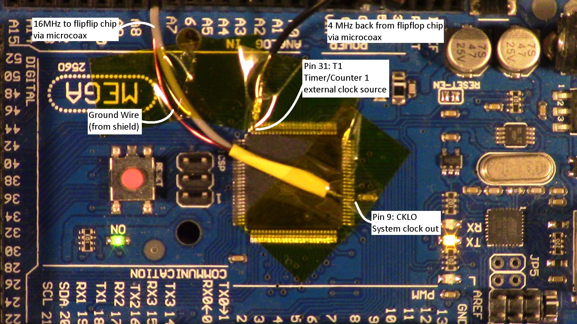
To divide the clock by 4, I'm using a SN74F109 I found in a bin of old ICs. This dual J-K flipflip operates up to 25MHz, and feeding the main clock into side 1 and the output of side 1 into side 2, we get a 4MHz signal that we can feed to the TLC5941s as the GSCLK signal as well as the input for our update counter.
I'm using some microcoax I salvaged from a dead wifi router in an attempt to control the electrical noise that these clock signals put out. Of course everything is interfaced via cheap breadboard so it's not much help, but maybe when it's all put together properly...

Teeny tiny! This is from an early test to make sure the clock signal was getting out...
Speaking of; By default, CLKO is not active, and there is no signal on pin 9 (unless you write something to port E pin 7). To make this magic happen, we need to reprogram the fuse bits in the Mega 2560 and enable it. To do this, we need to set bit 6 of the Low fuse byte to 0 (default = 1 = pin acts like a normal port pin). I did this by using an Arduino Uno as an ISP and loading up AVRDude in terminal mode (via Windows command prompt:)
avrdude -p m2560 -c avrisp -b 19200 -P COM9 -t
Change COM9 to whatever port your ISP is using. Once AVRDude connects without errors or warnings, read the LFUSE byte:
d lfuse
By default, the Arduino Mega 2560 sets the fuses to 0xFF, or 0b11111111. We want to set bit 6 = 0 to enable CLKO, so our new value is 0xBF.
w lfuse 0 0xBF
Apply and exit, and we're done! Be very careful fiddling with the fuse bits; you can accidentally brick your Arduino if you accidentally, say, set your system clock to an external source and now there's no system clock to program it with. You'll find more information about the LFUSE bits in Table 30-5 of the ATMega Datasheet.
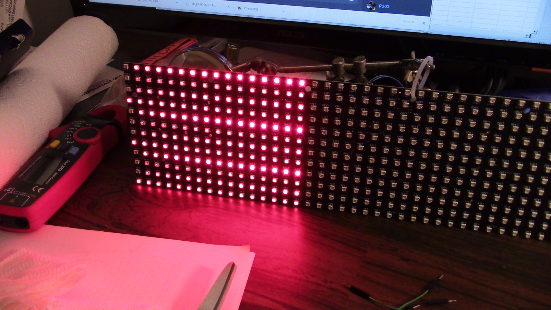
Anyway that's it for this update. Right now it's displaying test patterns at a whopping 120Hz refresh rate and even dimmed LEDs are shimmer-free to both eye and camera!
Discussions
Become a Hackaday.io Member
Create an account to leave a comment. Already have an account? Log In.