I have a few sets of these cheap led strings that I happend to purchase in a UK supermarket (Aldi). The original set that was purchased lasted a few years but the new ones seems to fail after a year. After the Chistmas season was over I decided to investigate further with the aim of reparing the string. After all how hard could it be.
The sets I have are as in the title photo. They each are 360 leds with a small controller with two buttons, one of which illuminates to show the timer function is active. They didn't cost much but I wanted to see why they failed.
Of the two sets that failed they looked the same but there was a difference in the power supply. The 1st set had a 5V power supply where as the 2nd set had a 31V supply. I did think this was odd and became one of the questions to look into. Other than this both sets looked and perfomed the same.
The failure mode was that there was a bunch of leds not working but all the others were. In one of the sets the leds in an area would flicker but again the others in the set would be operating as normal.
So for me the 1st step was to work out how the leds are driven. below in Figure 1 is the schematic of how the leds are wired in a serise / parallel arrangement.

There are two wires coming from the controller and they drive all the leds. The controller looking at the schematic drives the leds one way then reverses polarity to drive the remaining leds. To understand how this works lets consider a simple led string with 4 leds like in Figure 2

In Figure 2 if we make T1 more positive than T2 all the 'A' leds will be forward biased and with enough voltage they will illuminate. For the reverse of this making T2 more positive than T1 and with enough voltage all the 'B' leds will illuminate. So with this knowledge the controller is swapping the drive voltage between T1 and T2 in order to control which leds illuminate.
After working out the wiring, this led me to think about about failure modes. I came up with a list of 5 failure modes for the whole string as shown in Figure 1.
List of Failure Modes.
1) A break in the cable between segments or on the supply / return wires will result in the whole LED string not working.
2) A break in the cable within a segment, will result one or more LEDs in that segment not working. The remaining LEDs will carry more current whcih could lead to them buring out and cascade failure of that segment.
3) A short accross one led caused by either LED failure or something like corrosion between LED leads will cause all LEDs in that segment to not work. The remaining segments will see a higher current whcih could cause cascade failure.
4) A open circuit LED will just cause that LED to not work. The remaining LEDs in that segment with the same polarity will see a higher current. possible cascade failure if LEDs are driven hard or there are multiple type 4 failures.
5) The LED "works" but is damaged either due to being overdriven or more likely poor LED quality. This LED can have a high turn on voltage or reverse leakage issues. The other segments will light normally but the segment with this LED will have dim LEDs in the remaining part of the segment.
At this point my curiocity got the better of me and I decided to reverse engineer the controller. Here are some photos of the controller and the PCB inside it. I removed the EEPROM (IC2) as I wanted to read what was in it. This was not as exciting as I hoped for, it turns out the microcontroller stores the last used pattern in memory location 0. The rest of the EEPROM is not used. The manufacturer clearly got a deal on the Atmel 2Kbit part as they don't need that capacity.
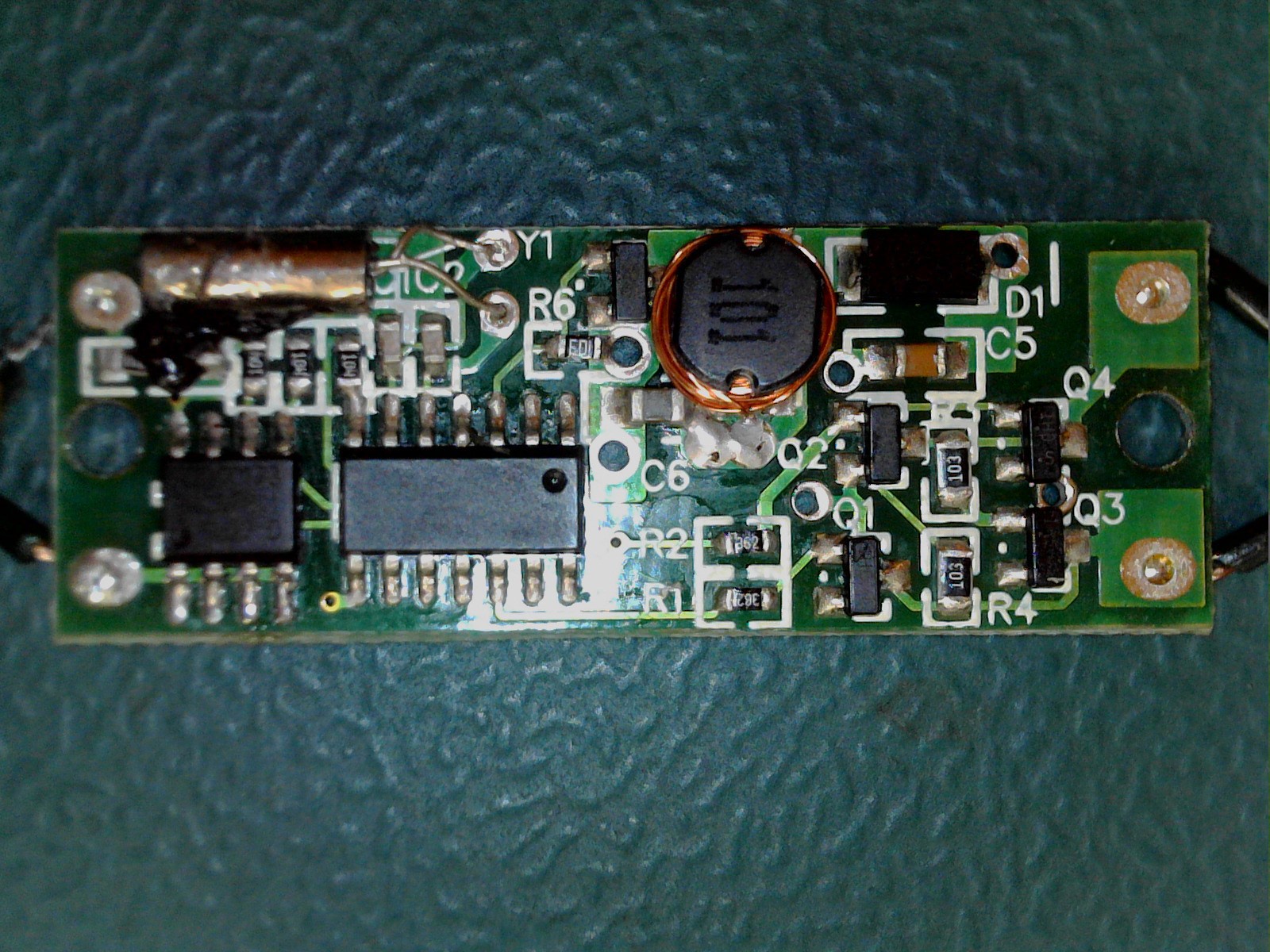
Generic no name 14 pin microcontroller, Atmel 2Kbit I2C EEPROM, and a bunch of passives and some transistors.
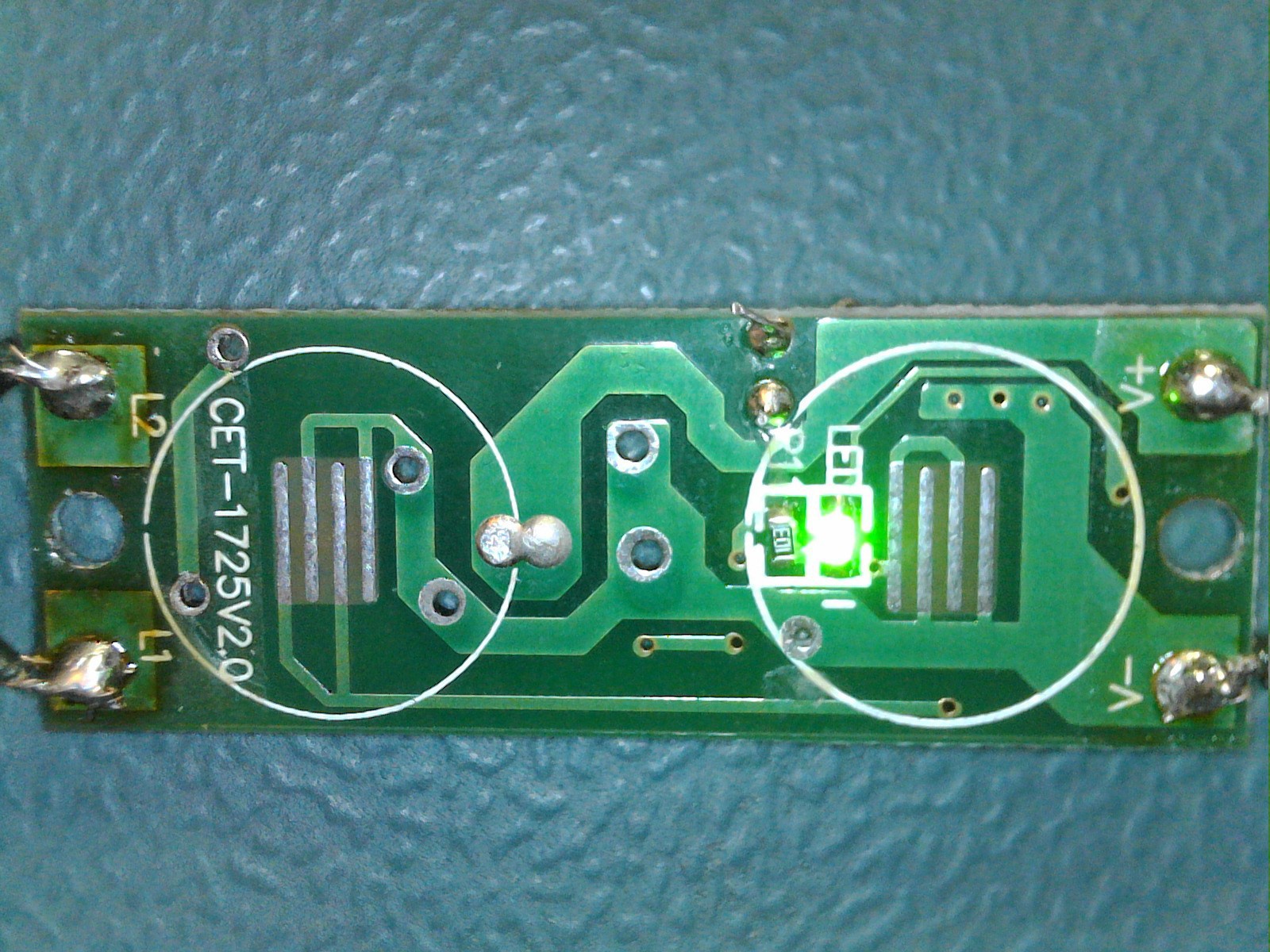
The pushbuttons are the conductive rubber type that make contact to some traces on the PCB. One of the buttons has the green LED to illuminate the rubber button when the timer function is active.
From this I produced the following schematic in Figure 3.

The circuit is quite simple but it did take a bit of searching to identify the Microcontroller and transistors. All datasheets are attached if anyone is interested.
The main circuit blocks are EEPROM which stores the last pattern the user selected, Microcontroller, Boost power supply and H - Bridge to drive the LED string.
I found it interesting that the designers decided to implement a boost circuit to take the 5V up to around 20'ish volts. This is the difference between my two sets, where my 2nd set operates the same but has a 31V powersupply. I havent opened thast controller but highly suspect there is just an linear regulator or buck converter to drop the 31V down to 5V for the Microcontroller.
Once all this was done I needed to move onto fixing the led string. The controller worked with no problems so the fault(s) were in the string.
To find the failed led, I ran set of lights on the setting that illuminated all leds at the same time. I could quickly find the segement that was not operating. For this particular fault none of the leds in a segment worked at all so from my list of faults this was probably a type 3 fault. In my case I noticed that some of the leds in the failing segment illuminated so dimly that it's not visable without complete darkness. Looking along the segment it seems to get dimmer then brighter again. I removed the dimmest led and the rest of the segment illuminated correctly. I replaced the led to ensure the current balance was correct and to prevent possible cascade failure.
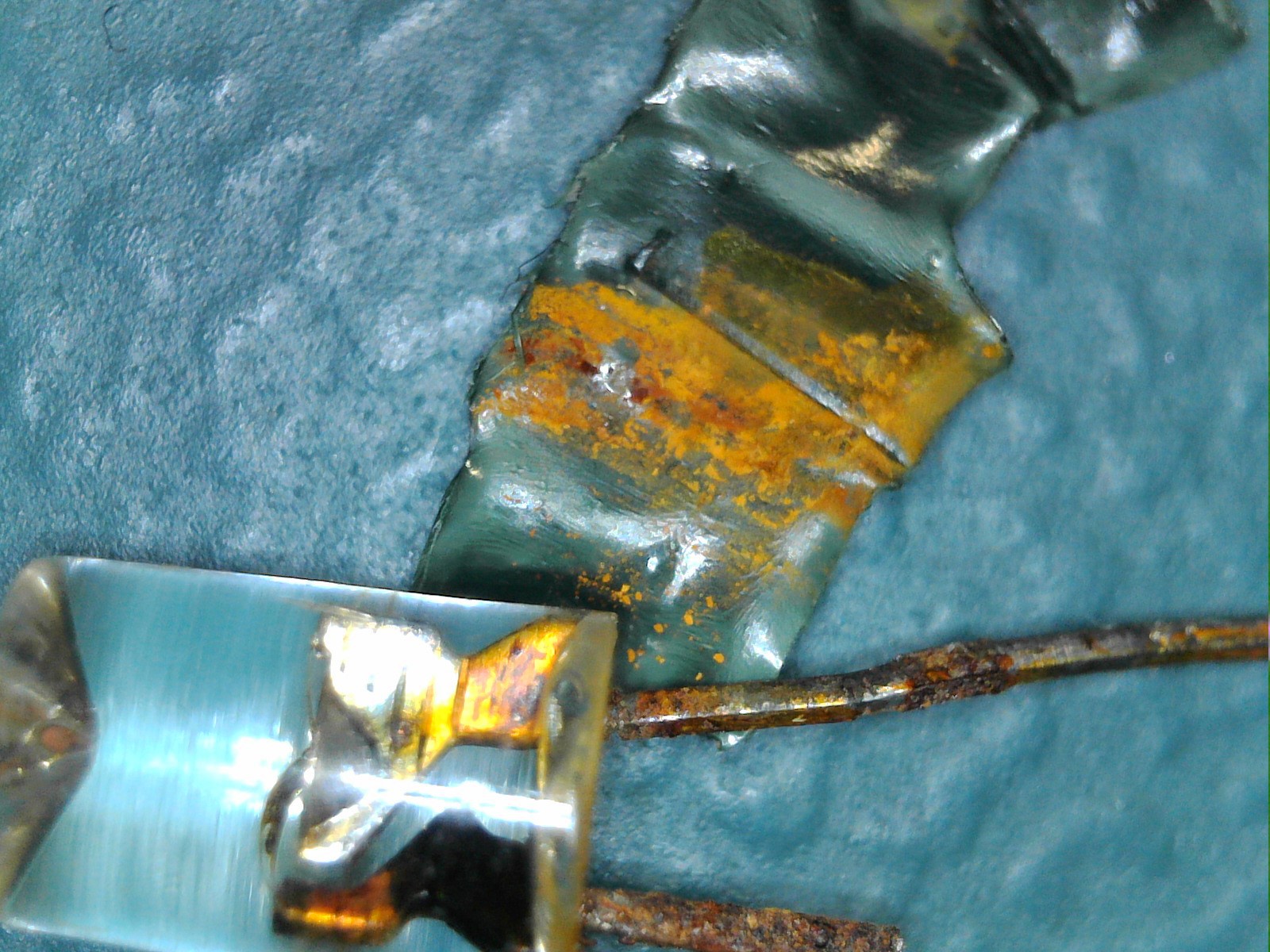
Here is a picture of the failed led. We have been using the set outside and clearly water had caused corrosion of the leads. The corrosion caused a short. Under my microscope the corosion as also entered into the led package so this led was doomed.
Onto the 2nd set of lights and they had 2 different failures. One segment was not working and another would flicker. The same technique was used on the segment that wasn't working at all and found the led that was off or very dim compared to the others in the segment. Removing this led made that segment work again and I replaced the led with a new one.
For the last segment that was failing the failure mode was a little odd. The segment would workinitially but would occasionally go to half brightmess or just flicker. This seems to affect half the leds in the segment so I know from the simple led string in Figure 2 that either one or more leds in the 'A' leds group or 'B' leds group was failing.
I connected the string up to the bench power supply and set the voltage to a level well below the operating voltage but high enough to start an led in the failing segment to illuminate. Looking at the other leds in the segment I again found one led where it wasn't illuminating to the same degree. This was actually quite hard as the difference was minimal. In the end I used my USB microscope as light sensor and turning down the bench power supply to make the led just glow in complete darkness. I checked each of the failing leds and found the one that was dimmer than the rest, removing it from the segment made the rest illuminate correctly. I put this as a type 5 fault as the led technically worked but was clearly damaged in some way which allowed it to pass some current in both the forward and reverse directions. Once the led was replaced the segment worked correctly with no flashing.
Summary
These cheap sets are cheap for a reason. The led quality is not good leading to early failures. The sets are not waterproof allowing water to cause corrosion. I'm going to look into some way of sealing the ends of the leds where the wires emerge to hopefully imrove the life span.
All the failures were casued by one led talking out an entire segment of leds or every other led in a segment.