 Dylan
DylanOk now for arguably the most important part of the camera: getting the lens mount functional
For some background, each lens mount has a different flange focal distance. This is rather important, because the shorter the flange focal distance, the more possible compatibility there is for mounting other lenses not originally designed for that mount. For example, the M42 screw mount flange focal distance is 45.46mm (apparently that’s Pentax’s number, but the original Praktica distance is 45.5mm), while the Nikon F mount flange focal distance is 46.5mm
What this means, is that only a small spacer is needed to attach a Nikon F mount lens to a M42 flange focal distance design. Doing the inverse requires additional optics, which is certainly not ideal. This is the reason why people have been using mirrorless cameras with nearly every lens in existence since there is no mirror to deal with. Since I intend this design to work with film and maybe a digital back in the future, mirrorless operation is not really feasible.
Right now, I’m just going to aim for the Nikon F mount, since I have a few of those lenses. Further down the line, I’ll work on shortening the flange focal distance for more compatibility. It looks like the Canon FD mount with a distance of 42mm would be an ideal target to aim for, since it appears to be the shortest distance with a reasonable amount of lenses available. Though I don’t happen to own any Canon FD mount lenses, so this wouldn’t exactly be great for development right now.
Ok, so flange focal lengths. Now what? Well, it’s trivial to parameterize the design from here for the focal lengths, so I started adding those in for modification later. And so the film/sensor plane and lens mount can be defined. Now the more interesting part: the light path from the lens to the film/sensor plane has to be the same length as the lens bouncing off the mirror, and then to the viewfinder. I am assuming this means the focusing screen, so I used that in the calculations.
Right now there is just an arbitrary mirror plane offset, just to make sure everything fits inside the body, but it would be nice to do a better calculation in the future.
The mirror of course needs to be at a 45 degree angle, but also needs to move out of the way in order for the film/sensor to actually get the image. I’m not entirely sure how I want to do this yet, but using a small slot for the range of motion works well enough. I’ll need to spring load this at some point, but not super difficult.
Here’s the transparent side view:
And a shaded view of the motion:
After testing this out for real with some overnight 3D printing, looks like everything is how I wanted it to be (first try!)
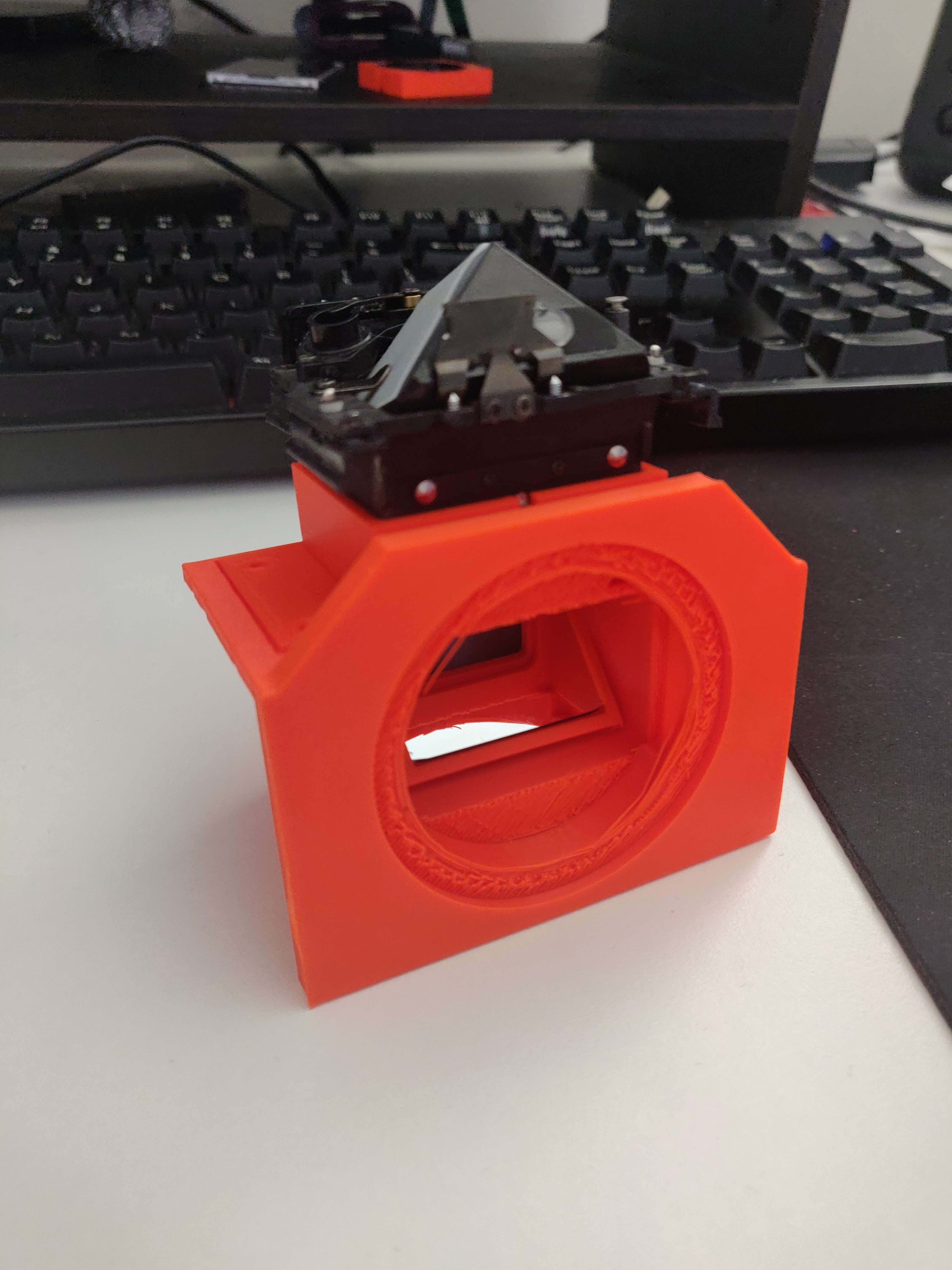
The mirror was a little annoying to fit in place, and I’ll need to figure out a better way to install it. I intend to use some shoulder screws instead of the posts which should help a ton, but I don’t have those yet so this is good enough. Since the slot for the mirror is at the top, the swinging motion will keep the mirror in place, so I don’t think it would need much for keeping the mirror from accidentally falling out otherwise.
And for the full test with a lens (that I had to hold to the mounting point since there is only a gap for one right now)
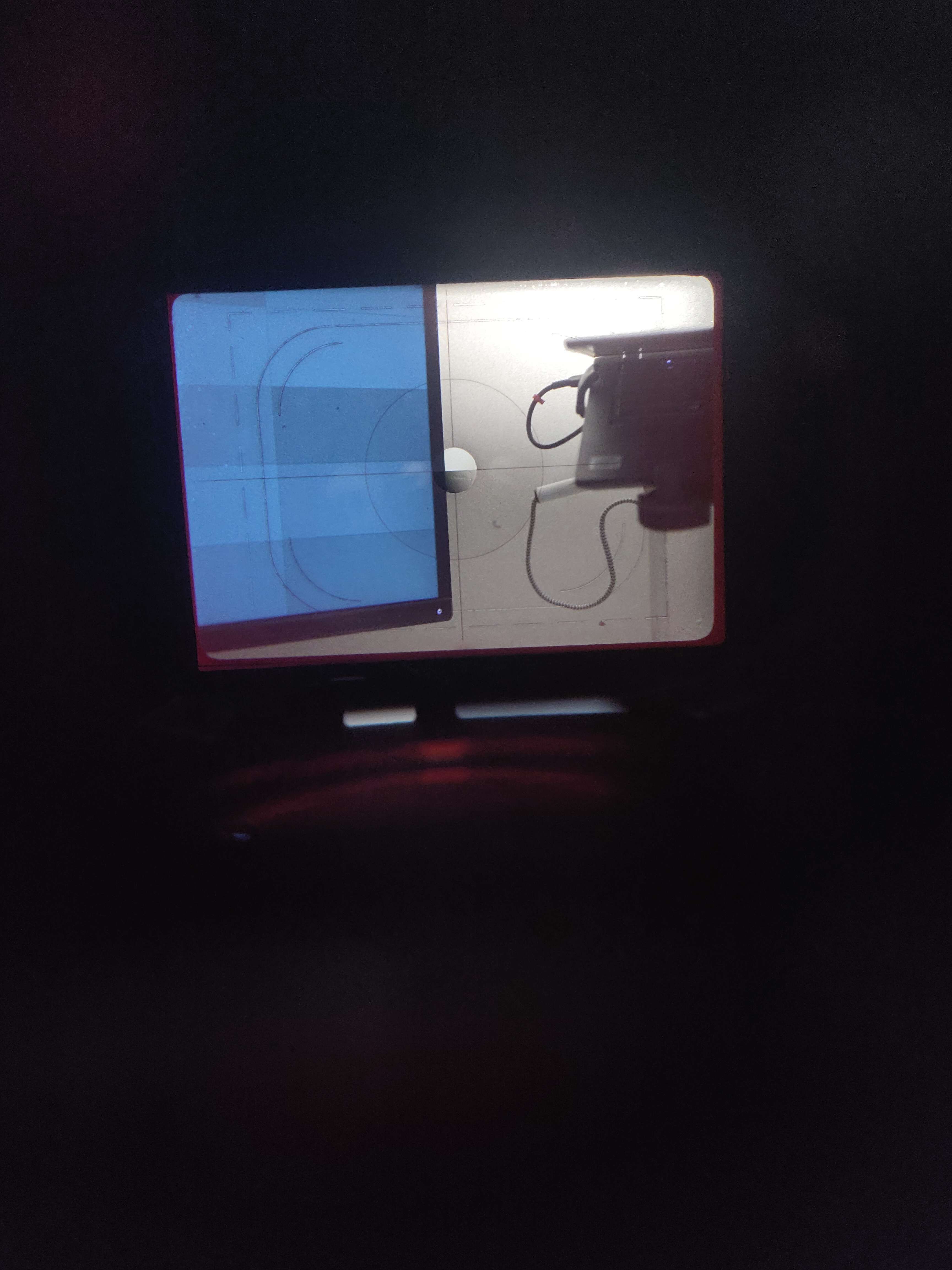
It works! Able to adjust the focus ring of the lens, and get the split lens in the center to focus! This final pic was taken from my phone looking through the viewfinder, and holding the lens in place. Rather cool to get this far in only a day and a half’s worth of work
Discussions
Become a Hackaday.io Member
Create an account to leave a comment. Already have an account? Log In.