 Nguyen Vincent
This first prototype was designed with the following specifications
- 65% layout (with additional macro keys or F-keys on the left side).
- PCB can be broken off to reduce it to a 60% layout.
- Designed around the nRF52840 MCU to be compatible with the ZMK firmware.
- Can support 3 solar panels per half.
- Optional rotary encoders on the top corners of each half.
- Optional hotswappable 5-way navigation switch/ mx switch / horizontal rotary encoder near the thumb
- Compatible with e-ink paper display.
- Reliable protection circuit.
- Battery monitoring.
- Two USB port per half to allow for charging both halves at the same time by connecting one to the computer and the two halves together.
To meet these specifications, 6 different PCBs were designed.
Main PCB
The MDBT50Q-1MV2 module from Raytac was used in this project. This is a very interesting module as the DCCH, VDDH, VDD and VBUS lines are all broken out. This allowed me to design the chip around its high-voltage mode, which is very useful as the internal DC-DC converter can be used. A very interesting feature of the nRF52840 is that it switches between its internal LDO and its internal DC-DC converter to maximize efficiency.
The board is also is equipped with the BQ24075 lipo-ion charger. This chip is interesting because of its interesting sets of features:
- a selectable 100mA or 500mA charging current, which is ideal for charging with USB port
- SYSOFF input, which enables the user to turn off the keyboard with an SPDT switch. This has as an advantage that when turned off, only the battery is disconnected, but the user can still use the keyboard via USB. The disadvantage is the increased power consumption, as the chip has internal pullups on the SYSOFF input.
- Thermal shutdown protection. By connecting a 3-wire battery (with the third wire being the thermistor), it's possible to shut down the system when the battery gets too hot. To make the PCB as versatile as possible, it can also support 2-wire batteries in which case a jumper has to be closed, which connecting a 10k resistor to the thermal shutdown input.
For battery protection, the AP9101CK6-ANTRG1 IC was chosen. Most people might go with the TP4056 + DW01 combo but the DW01 has its under-voltage lockout protection way too low (2.4V), which makes it useless for a standard 4.2V lipo. The AP9101CK6-ANTRG1 has its under and over-voltage cutouts at 3.4 V and 4.225 V respectively, which is much better.
To further protect the board, the USB-C inputs are protected against ESD events, reverse voltage/input, reverse current and over voltage. The LTC4359 ideal diode controller was used for highly robust protection. This might be slightly (or very) overkill for a keyboard, but I had some on hand so why not.
For the energy harvester chip, I chose the BQ25504 as it could harvest very low amount of luminous energy (even from indoors light) and had very low quiescent current. It also implements maximum power point tracking (MPPT) to maximize its energy harvesting capabilities.
To measure the battery voltage, the MAX17048 fuel gauge is chosen. This is a very inexpensive chip which communicates via I2C. I'vr chosen this chip instead of the classical voltage divider solution because of its high precision during charging phase. Indeed, lipo batteries tend to have non-linear charging curves, which could make determining the state of charge more difficult with a voltage divider. Another interesting characteristic of this chip is that it does not use any sensing resistor, which makes its footprint on the board very small.
As you might have noticed, there is a large switch near the bottom half of the board. This is a 6PDT switch, which makes it possible for the user to choose between a 5-way navigation switch or an horizontal rotary encoder (EVQWGD001). They are connected to different parts of the switch matrix, and connected to the main PCB with a 6-pin JST-SH connector.
The PCB can be broken off on the sides while retaining its core functionality for a reduced layout.

E-ink paper display breakout
It's designed for the Waveshare 1.02 inch e-paper display module. This display is quite interesting as it consumes almost no current when not refreshing, which makes it perfect for a battery-powered application.
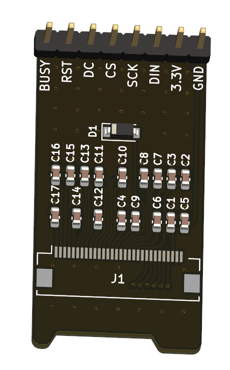
It's connected to an adapter board as shown below. This board is crucial to provide mechanical support in the keyboard case, as I wanted the display to sit as flush as possible against the top of the case.
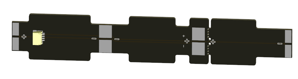
Solar panels
A very simple-looking PCB, which is however more complicated than it seems. The shape of this PCB is very important as the flaps serve as mechanical support against the top of the case. Indeed, the solar panels need to be flush against the top of the case to maximize efficiency, which made the design quite more complex as I wanted to have no visible screws from the top. As such, each pad here has many vias which makes it possible to solder the solar panels from the other side while pressing them against the top of the case.
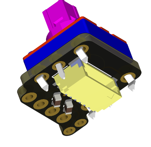
External connector
This PCB is used to connect either a 5-way navigation switch or horizontal encoder. Its shape is quite tricky, as it needed to fit inside a 1u switch (19.5 x 19.5mm) max. It exposes a 6-pin JST-SH connector which can be connected to the main board.
Discussions
Become a Hackaday.io Member
Create an account to leave a comment. Already have an account? Log In.