 Peter
PeterHello, i tested my control unit using a logic analyzer to be sure that the system runs how it should run...
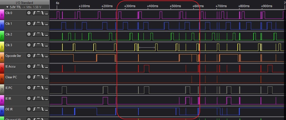
1) Start-Phase
What you see in the next picture is the start phase, the first clock cycle. Remark: after switch on of the system a IR_C (Clear instruction register) has to be done by hand. Then the clock is allowed to start:
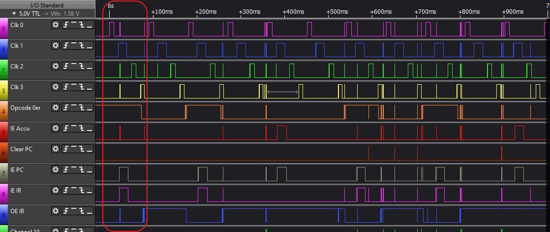
Important for an understanding is the signal Opcode_0er. It is active if no valid opcode is stored in the instruction register (IR). The following circuit diagram shows the design of this signal and the output enable of the instruction register (we have to deactivate OE of the IR if no valid opcode is stored in the IR):
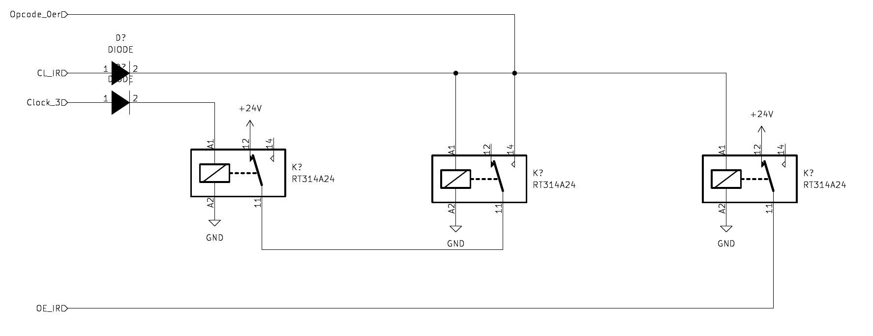
Opcode_0er ist set if the IR is cleared, which happens in case of an IE_IR (during Clk 1) during Clock 0 (in the first clock cycle we activate IR_C by hand). Opcode_0er is later deactivated during Clk 3, because now we should have a valid opcode in the IR.
And we need Opcode_0er for an ancor in the state machine, for example in the NOP command (but its the same in all commands):
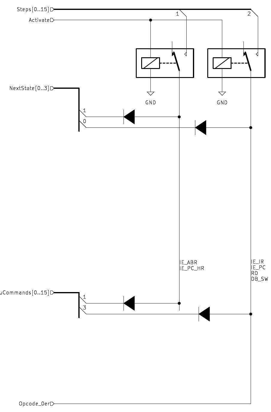
Opcode_0er acts like the last state of a command, responsible for input enable instruction register.
2) NOP command, 2 cycles
Here you see the two cycled of the NOP command.
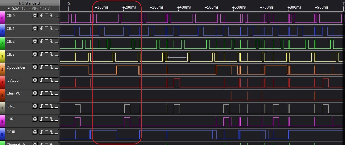
3) LDA X command, 4 cycles
The LDA X command is loading the accumulator register with the value stored in the memory adress after the opcode, then the next opcode is loaded into the IR (this last cycle is the same for all commands, also for the NOP):
Discussions
Become a Hackaday.io Member
Create an account to leave a comment. Already have an account? Log In.