 Peter
PeterIf only the control unit was running, receiving the opcode of a command directly from the arduino which generates the clock signals, the timing of the system was very fast. A NOP command was finished within 128ms.
But the connection of a memory based on a arduino changed the situation. Now the timing is more difficult...and I tried to figure out what is happening, because the system now runs perfect with high speed and sometimes, could be after 10-20 commands, it crashes.
The following tests were made with a slower speed, the system was running very stable, without any crash.
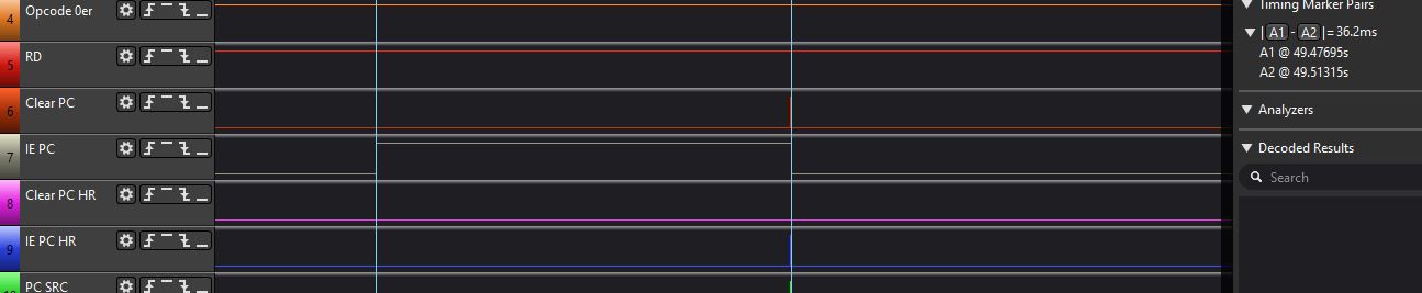
Here you see a logic analyzer picture of Clock 1:
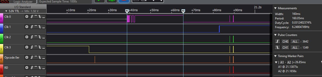
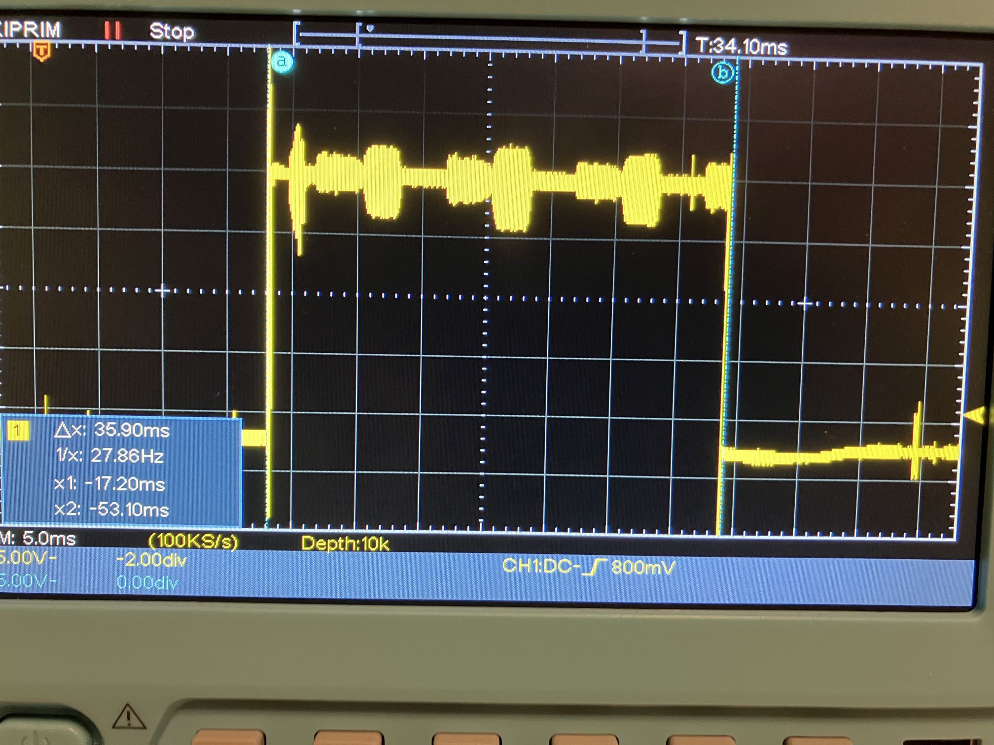
You see a interesting thing: the signal of Clock 1 looks not very good. The rising edge of Clock 2 for example looks much better. The signal time of Clock 1 was 26,8 ms, which is not very fast. The fastest Clock 1 time I tested (without a memory module) was 7ms. I was not sure if the signal realy looks that way or maybe the logic analyzer is showing something wrong. So I used a Oszi:
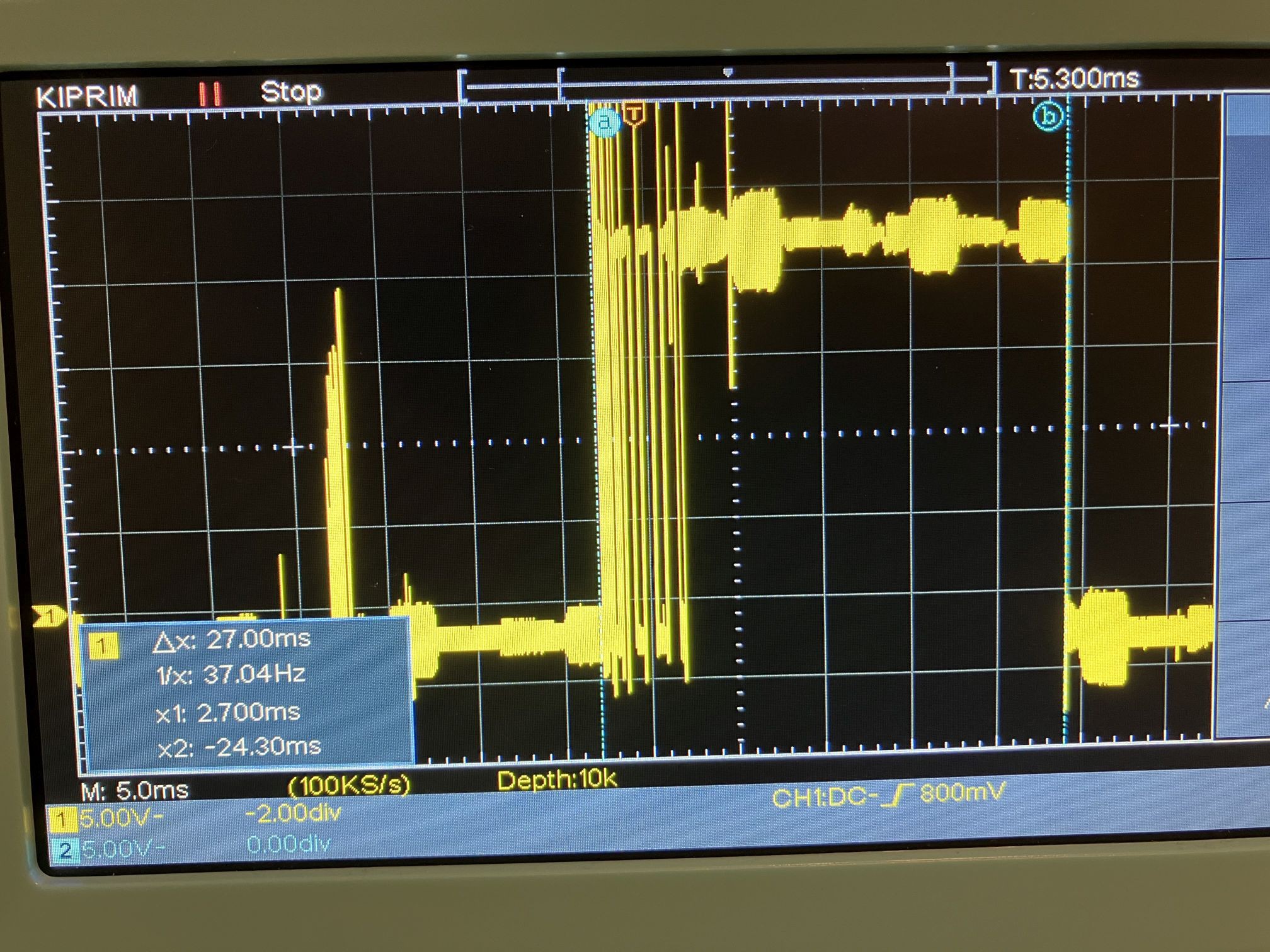
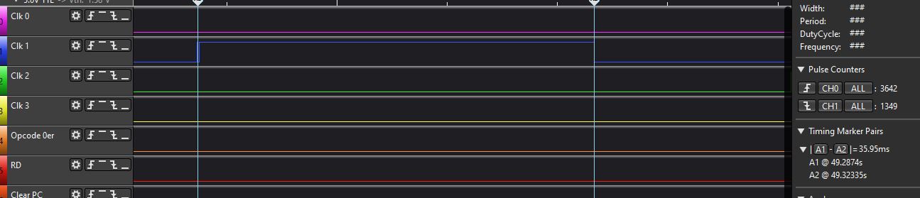
The first thing to notice: the timing measure is very accurately. The second thing: The signal does not look very good, even on the Oszi. If I reduce the signal time to 7ms no stable state will be reached. I checked another clock signal, Clock 2:
and the Oszi picture:
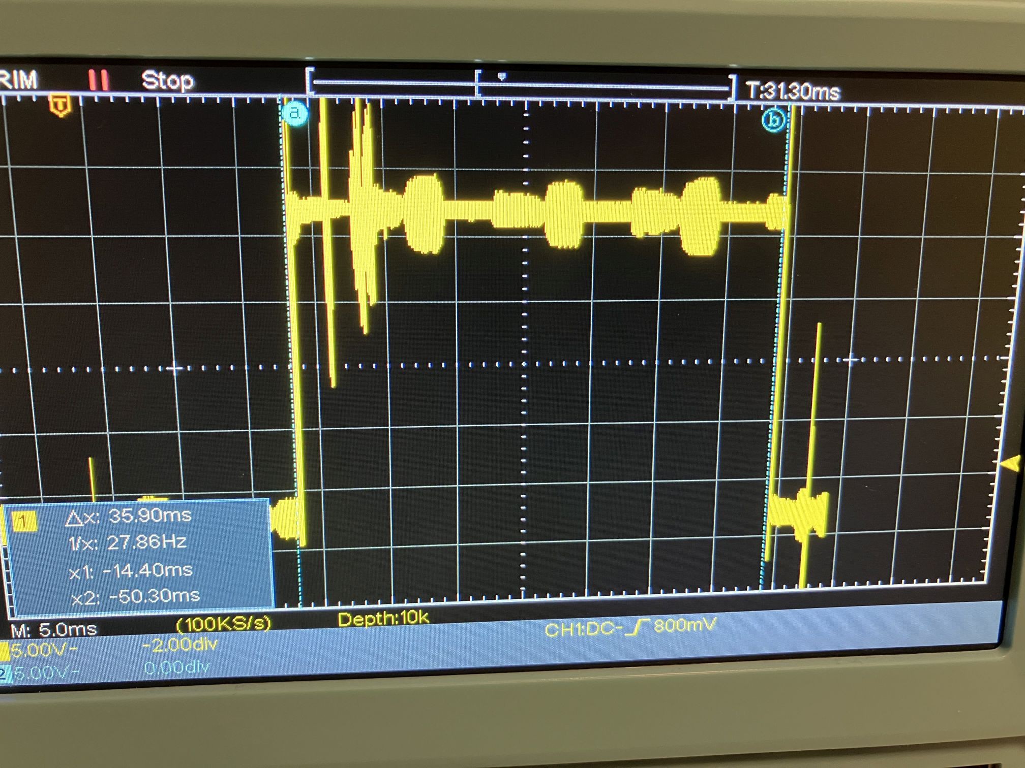
This Clock looks much better, in the logic analyzer and in the Oszi (Clock 2 is 10ms longer in High than Clock 1, this is correct).
The last signal I checked was the input enable of the program counter:
looks perfect in the logic analyzer. The Oszi measures:
Thats an excellent signal.
What is the result of the measurement? The relays have very different quality, and the relay generating clock 1 seems to be one of the worse relays. I will change the output relay of Clock 1 and see what happens.
Discussions
Become a Hackaday.io Member
Create an account to leave a comment. Already have an account? Log In.