 Peter
PeterSo, I measured the timing behaviour of the relay using an oszi. This was my test setup:
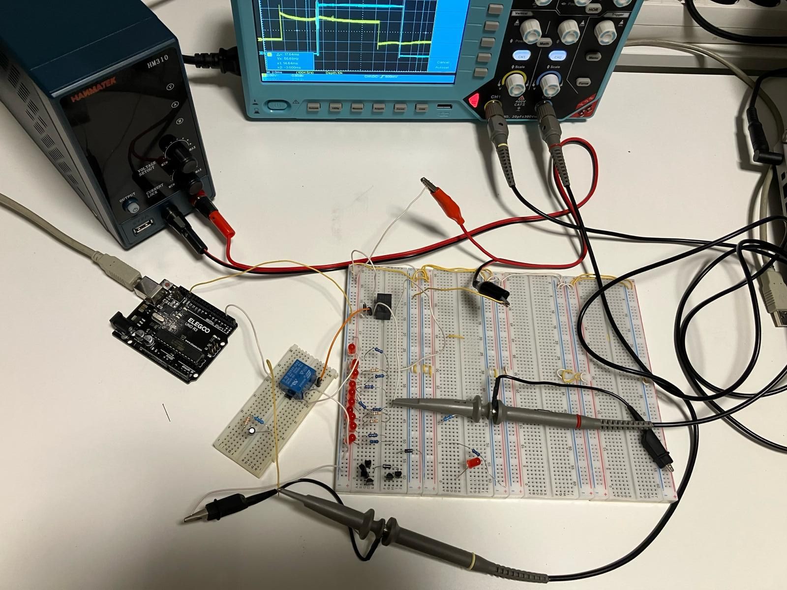
I used an arduino to switch on/off the blue relay (its the same type than the relay of the timing module and the memory module of the relais CPU) using the 5V of the arduino, the blue relay is using its switches to switches on/off the black relay using 24V. The output of the black relay is connected to a LED.
The first two diagrams show the switching of the blue relay, yellow is the arduino signal, blue the relay output:
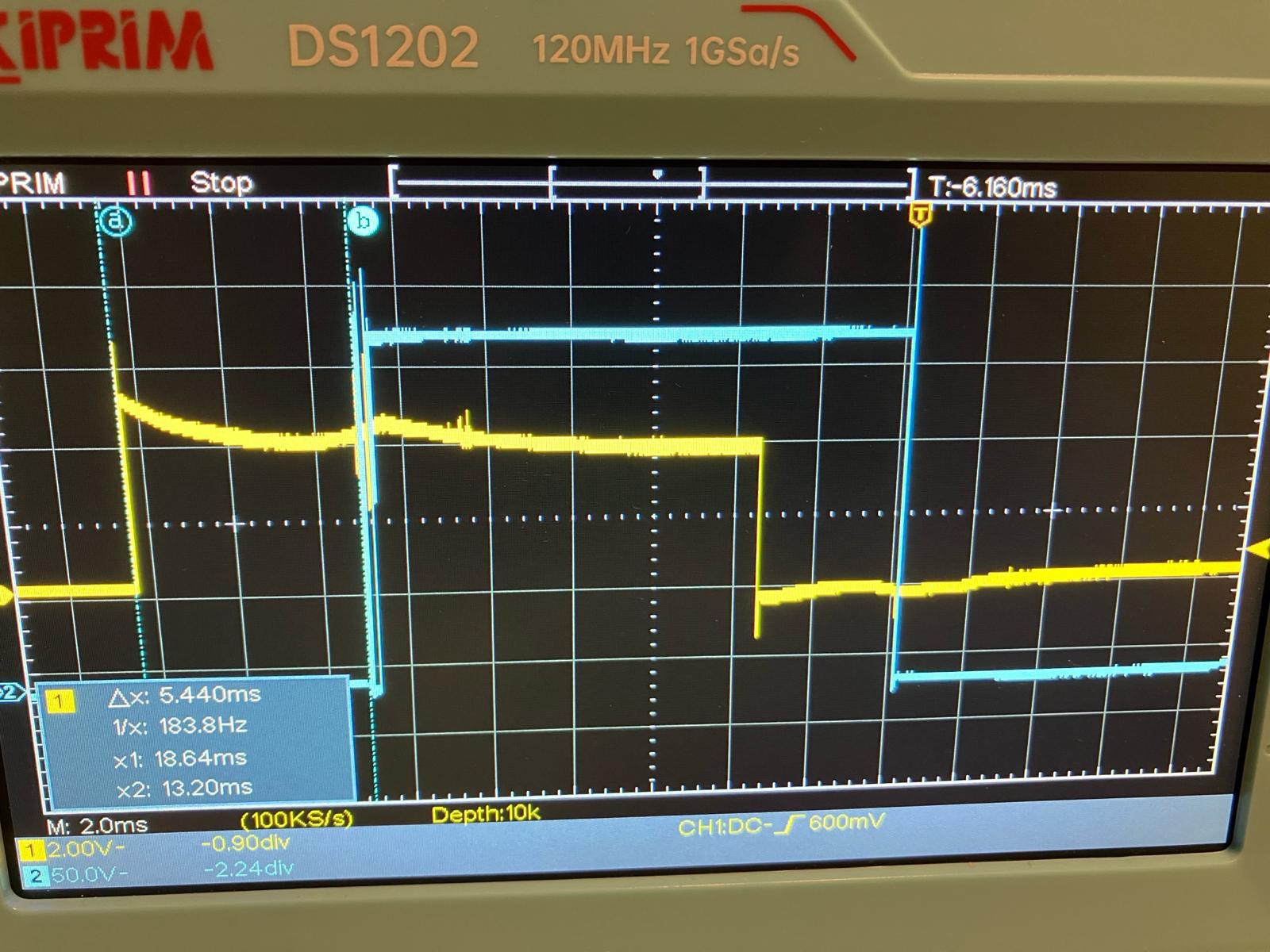
The switch on time of the relay is 5,44ms.
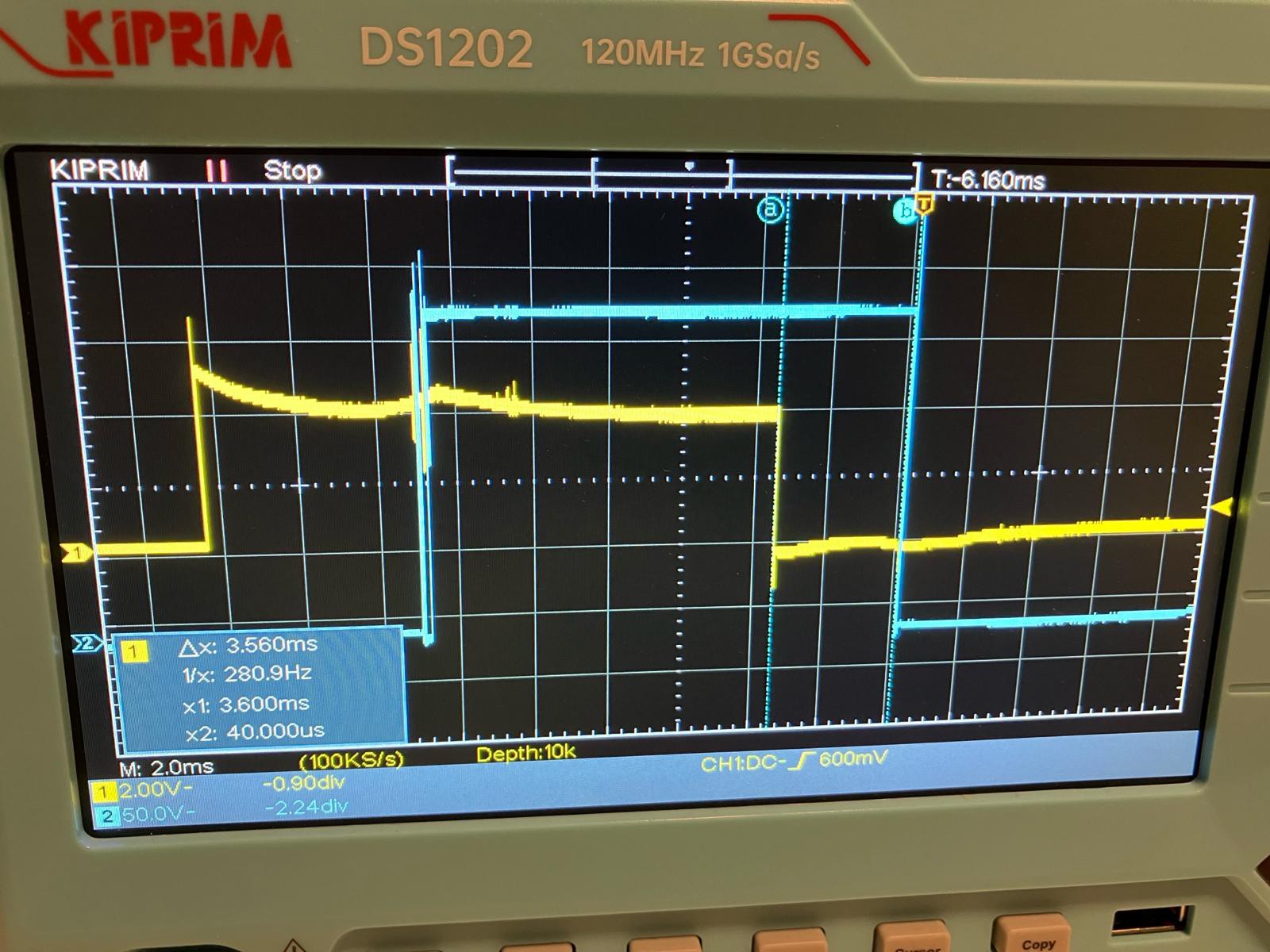
The switch off time is 3,56ms.
Now the measurement of the black 24V relay. which is much more important...because this is the relay which is used for 90% of the relais CPU. The blue 5V relay is only used as an arduino output for clock and memory.
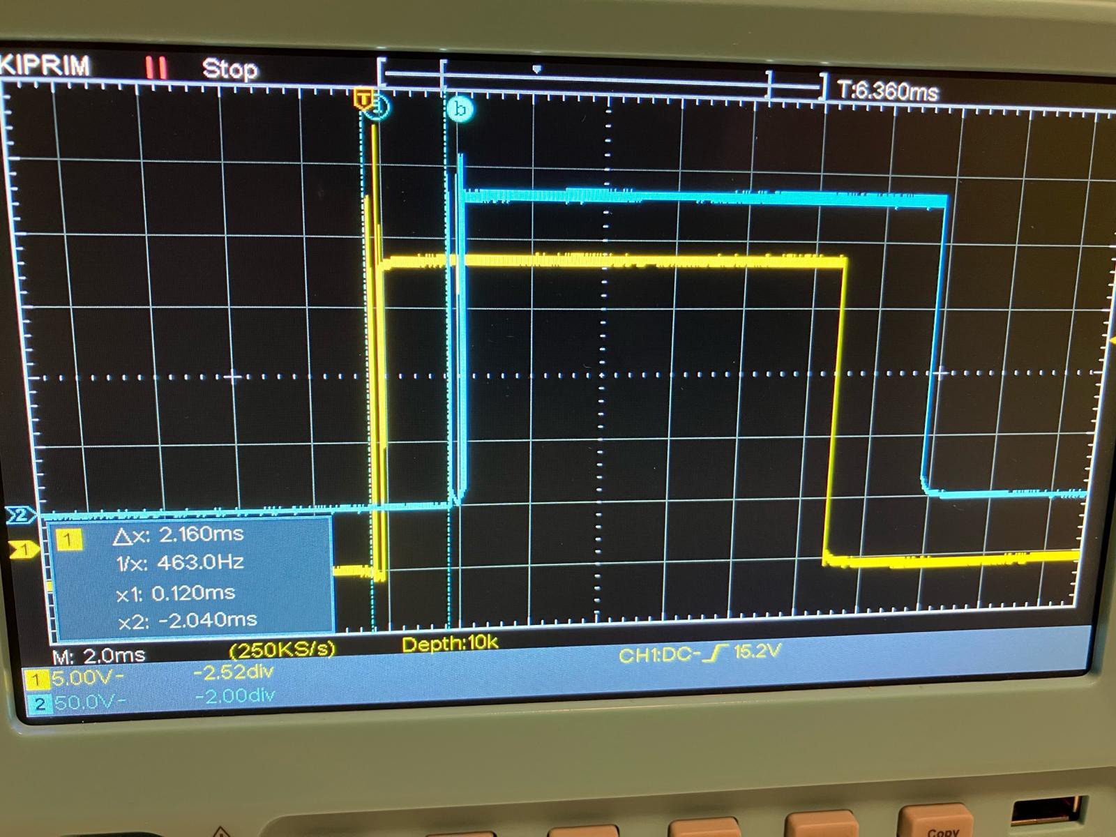
The switch on time of the relay is 2,16ms, thats very fast. The bouncing of the relays is visible, but not a very big problem.
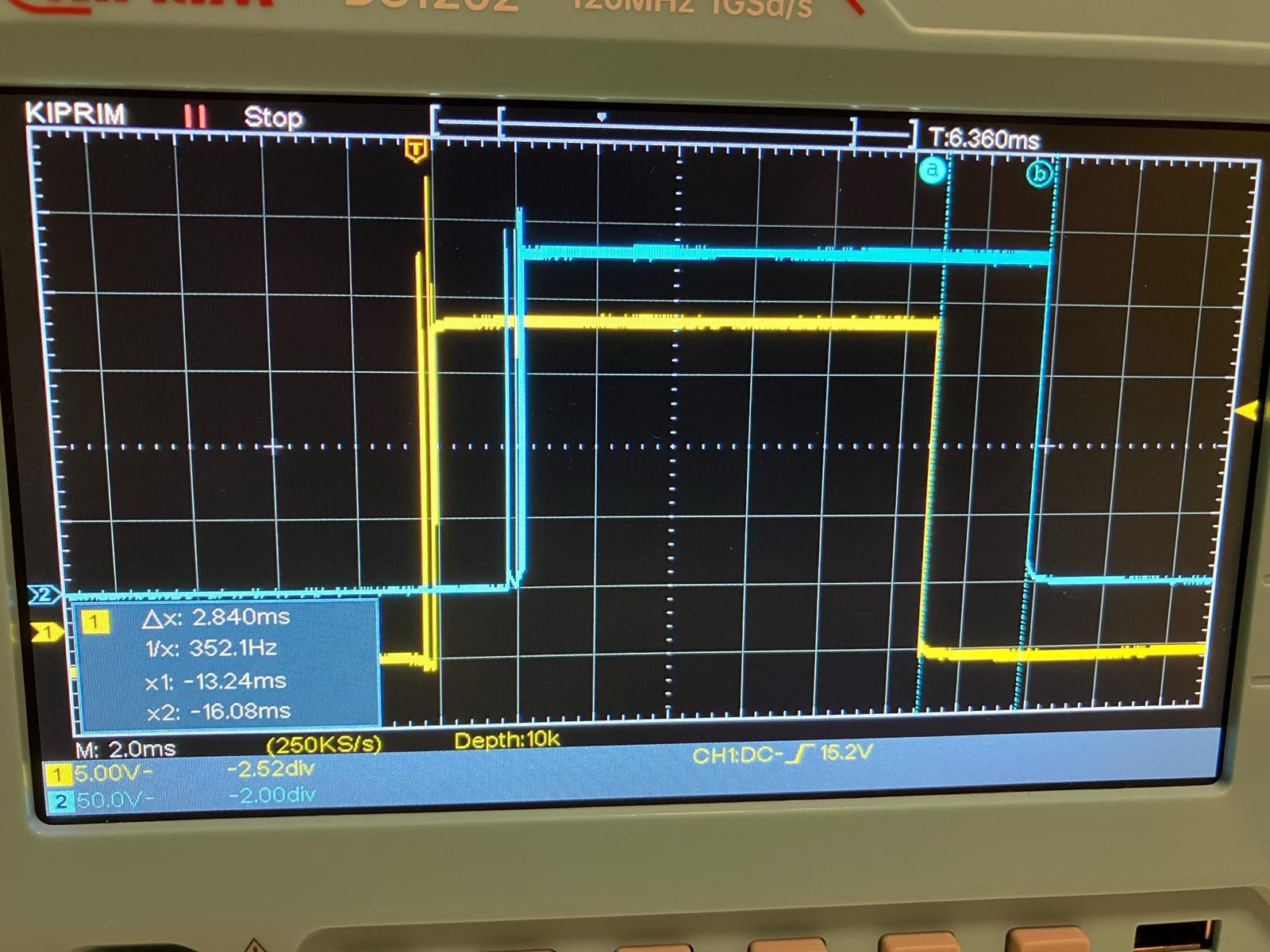
The switch off time is 2,84ms...also very fast.
Summary of the test: the used relays are faster than I thought!
Discussions
Become a Hackaday.io Member
Create an account to leave a comment. Already have an account? Log In.
I wonder if there are any tricks you can use with snubbers or flyback diodes to improve turn off speed. Although those are more for protecting drivers.
Are you sure? yes | no