The SelfScan was the visual output device for the MCM/70 computer. It could display one line of 32 characters, and it looked like this:
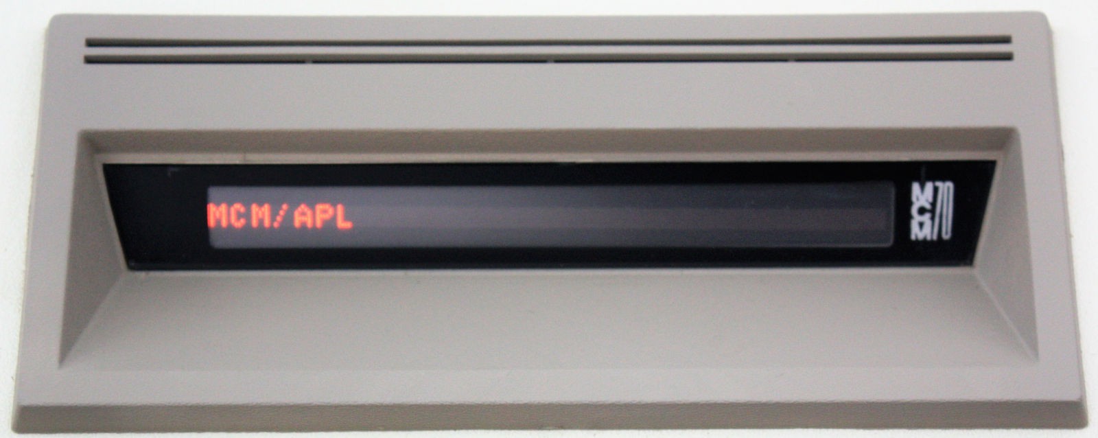
CRTs were available at the time but they were very big, very heavy and very expensive. Not great for what was intended to be a small, portable machine. The SelfScan, made by Burroughs, was a plasma display device with the method of operation similar in some respects to a Nixie tube. It was called a "self scan" because you didn't have to address the dots on the screen: after hitting it with a Reset pulse you then provided the 222 bytes of data in order and it "scanned" along by itself. It was actually pretty clever. Today it looks horribly dated but in the early 1970's it was quite reasonable. The version used by MCM provided a screen 222 pixels wide by 7 pixels high. Being memory mapped it allowed MCM to display all the special characters used by the APL language. You can see a scan of the SelfScan data sheet here (PDF). That sheet references a smaller model of 111 columns but the rest are the same.
In terms of interfacing, it is both:
- Simple: Only nine signals: Clock, Reset and 7 data lines.
- Fussy: Needs +250 volts, the clock is asymmetrical with specified high and low times, data has to be provided at precise intervals, you have to make sure you let go of the data lines during reset and for the first 15uS of each clock pulse, and you must be able to drive the data input pullups down to no more than 300 milliVolts.
And you have to implement this memory mapped device with a CPU that has no idea what DMA is.
The Interface Design
The schematic for the Rack8 SelfScan interface is here (PDF), while the logic for the 22V10 GAL is here. Looking at the schematic now it seems all very obvious. When I started working on the design it wasn't the least bit obvious. There were many iterations of trial and error, mostly error, before I arrived at the current, working, version. Fortunately most of the error was on paper - oops wrong edge, oops that's a clock too soon, oops the signal we need is now gone, oops that output needs to be clocked, oops we have no output to clear that flip-flop etc. etc. etc. Possibly because I am more of a software than hardware guy. But eventually I came up with the current design. Even then there was some debugging to be done at which time my old Bitscope was a life saver. I'll have to do a post on the Bitscope. The thing is at once tremendously useful but also tremendously frustrating.
Here be a photo of the working SelfScan interface:
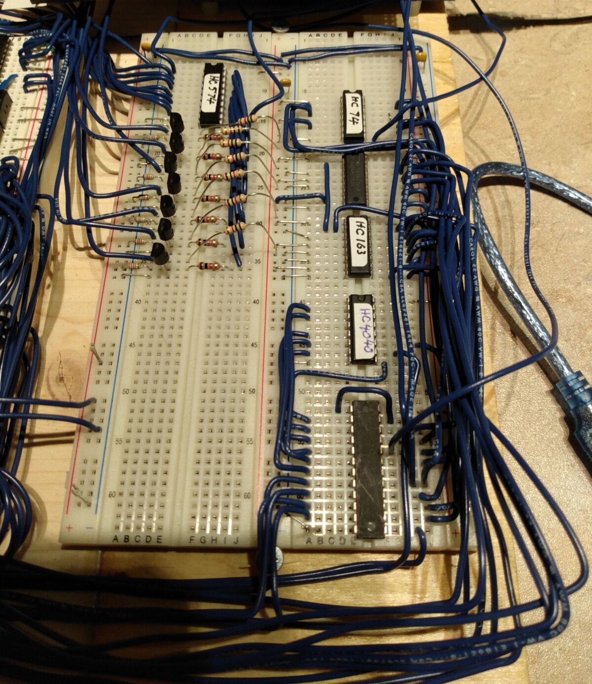
Counterclockwise from bottom right: the 22V10 GAL, the 74HC4040 Sync Counter, the two 74HC163 counters that generate the low 8 bits of the memory addres, the 74HC74 flip-flops, the 74HC573 data latch and finally the seven MOSFET transistors. Only six chips and a handful of transistors but it was a tricky design.
How it Works
Let's start with U19, the Sync Counter. It is a 74HC4040 12-bit ripple counter although in this application only the low 6 bits are used. It is clocked by the SYNC pulse from the CPU which is chugging along at 400KHz or 2.5uS per cycle. The clock is negative true so we use SYNC.H as the clock.
This Sync Counter is used as a time base to make sure that things happen when they are supposed to. In particular, to keep the SelfScan happy we need to:
- Clock it with a signal which is high for 115uS and low for 25uS.
- Issue a negative-true Reset pulse which is True for one clock period.
- After the Reset pulse is over, present data on the data inputs which have pullups and must be driven open-collector or open-drain.
- The data inputs must be left to float high during the entire reset pulse and for the first 15uS of each clock period.
So the low 6 bits of the Sync Counter are fed to the GAL. When the Sync Counter gets to 56 it is reset by the GAL. 56 x 2.5uS = 140uS which gives us the correct period for the SelfScan Clock.
For the first 10 counts, aka 25uS, the GAL makes the clock to the SelfScan low, for the rest of the time it is high. Bingo we have the clock for the SelfScan.
It is worth noting that the 74HC4040 is a ripple counter so you have to be careful to ignore the outputs just after it has been clocked. Toward that end, the GAL develops a clock for itself - based on SYNC from the CPU - which is guaranteed to be at a safe time. That clock comes out on pin 23 and is fed to pin 1 of the GAL to be used to clock those registered outputs that need to be careful.
Next up are U22 and U23, both 74HC163 synchronous binary counters which form the SelfScan Address Counter aka SSAC. They are clocked once per SelfScan clock. Probably best to explain how they work by starting at the end and then working forward. When the SSAC reaches FF it set it's RCO (ripple carry output) signal True. U3f inverts this and applies it to the LOAD.L inputs of the SSAC. At the next clock pulse X'21' (which is hard wired on the data inputs) is loaded into the SSAC. Why X'21'? Well the RAM area for the SelfScan starts at X'2022'. The memory system provides the high byte of the address while the SSAC provides the low byte. It is X'21', not X'22', because while the SSAC is at X'21' the Reset pulse is being applied to the SelfScan and during reset the address does not matter. So on the next SelfScan clock pulse after Reset the SSAC will be at X'22' and we will then present the data from memory address X'2022' to the SelfScan for the first column of data.
But we need to generate the Reset pulse to the SelfScan and we need to generate it after the cycle where the SSAC is X'FF' is over. Thus we feed the RAC.L signal to U21A, the "RCO catcher flip-flop" which is clocked by the SelfScan clock line. When the GAL sees the output of the RCO catcher go true it know it's time to to start a reset pulse to the SelfScan. Then U21b comes into play. It is nominally a D flip-flop but here we are using it as a simple set/reset flip-flop. We set it to initiate the Reset pulse to the SelfScan and we clear it when the pulse is done.
Now there is the matter of getting data from the memory to the SelfScan. For memory mapped devices you might normally use DMA but the 8008 CPU has no clue about DMA. Instead we use what might be called SMA: Stealth Memory Access. Basically we access memory for the SelfScan when the CPU isn't looking. When the CPU is halted, or waiting (ie during single stepping) then the address and data busses are free and we can use them with impunity. When the CPU is executing instructions we have to be more careful. Every 8008 CPU instruction starts with T1 and T2 cycles, when the CPU is outputting he high and low portions of the address. Then on the T3 cycle it actually accesses memory. But during T1 and T2 the address and data bus are unused by the CPU. Thus during the T1 cycle we issue a pulse on the READ_SS.L line to memory which accesses RAM and puts the data from X'20xx' on the data bus, where xx comes from the SSAC. U18, our SelfScan Data Latch, receives the data from the data bus when clocked by the GAL. The GAL needs to know when the CPU is halted, waiting or doing a T1 thus we run the S0, S1, and S2 lines from the CPU into the GAL.
The Selfscan Data Latch is tri-state. When enabled, it drives the transistors Q1 through Q6 which in turn drive the SelfScan data lines. The SelfScan itself has 1.5K pullup resistors on its data inputs so we only have to pull them low; left to their own devices they float high. During SelfScan reset, and for the first 15uS of each SelfScan clock pulse, we have to leave the SelfScan data inputs alone to float high. We do this by disabling the SelfScan Data Latch outputs at which point RN3, a bunch of 22K resistors, pulls the gate of the MOSFETs low thus turning them off and allowing the SelfScan data lines to float high. We use MOSFETs because, when active, we need to be able to pull those lines down to no more than 300mV (per the SelfScan data sheet). There were other possibilities but it's always fun to have at least a few discrete transistors in play. And it works.
Discussions
Become a Hackaday.io Member
Create an account to leave a comment. Already have an account? Log In.