So we are developing a GPI board, which can be used as the basis for MCM peripherals, at least partly in order to test the breadboard implementation of the Omniport. But then we would like something which is itself capable to exercising the GPI board, and by extension, to help test any peripherals we might build based on the GPI board.
Operation on the Omniport is coordinated by the six control signals generated by the MCM/70 computer. Pulses on those control lines have a specified minimum time but no maximum time. Thus it's possible to do static testing on the GPI board and on quite a few peripherals as well. For example the Hytype daisy wheel printer used by MCM could be driven at slow speed because it will cheerfully wait any length of time for the next command.
The OmniTester is therefor a very simple device which allows a person to manually control the Omniport using switches. The schematic for the OmniTester is thus:
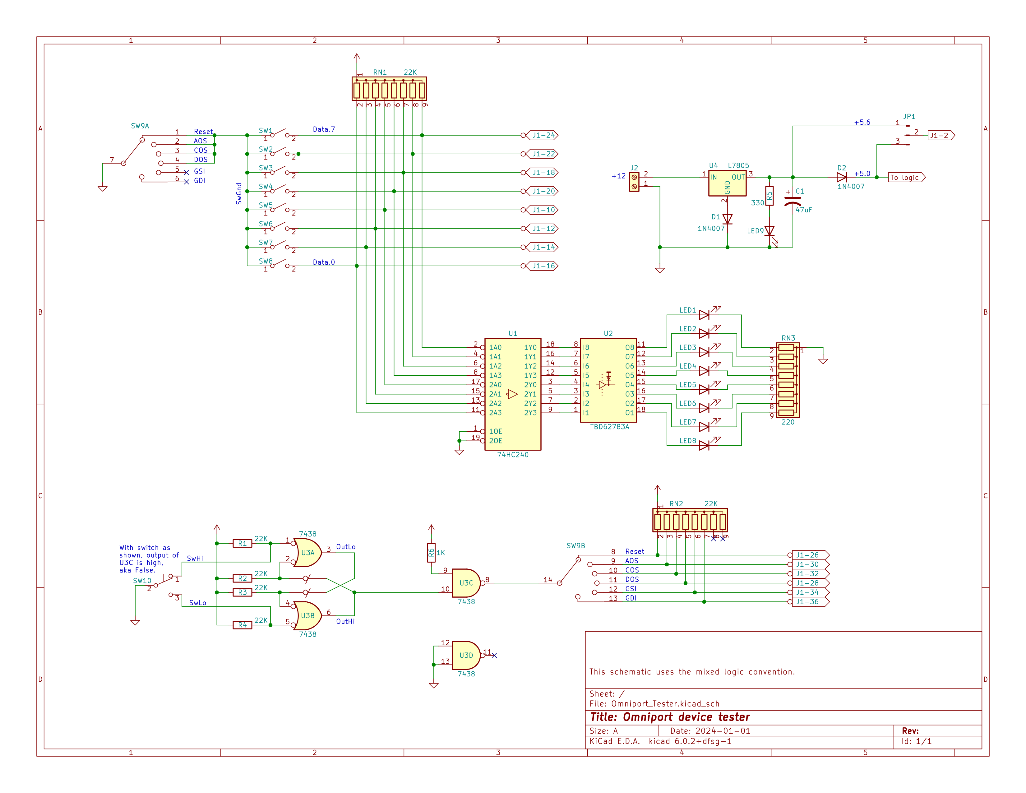
The signal from switch SW10 is cleaned up by debounce circuitry, just to the right, then - based on the setting of rotary switch SW9 - used to set one of the six Omniport control lines. Those control lines are negative-true so any control lines not set by the switch are pulled False by RN2. The Omniport data lines are buffered and then used to drive the LEDs so the user can see the state of of the data lines. Rotary switch SW9 also enables switches SW1 through SW8 for RESET, AOS, COS, and DOS so for those commands the Omniport data lines are driven by those switches. For GSI and GDI - where the data is coming from the peripheral - those switches are disabled.
At the time when I designed this tester I wasn't sure if the MCM/70 supplied +5 or +5.6 to the Omniport so the tester is configured to be able to supply either, jumper selectable. It turns out that MCM computers supply +5.6 so that it can go through a polarity protection diode thus resulting in +5.0 at the peripheral.
The OmniTester is so simple that I did a modest amount of testing then sent it off to be made into a PCB. In this photo:
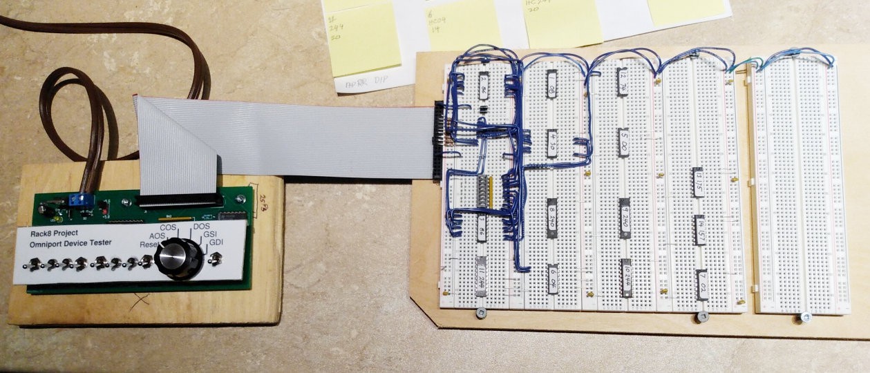
The OmniTester is the device on the left. The white panel with the legends is just thin plastic that floats above the PCB, secured by the switches. The single switch the right of the rotary switch sets the selected control line True or False, while the eight switches to the left set the data to be used. They don't show up in this photo but, on the board, just below each of the eight switches, is the LED that shows the state of the corresponding Omniport data line. In this photo the 40 pin ribbon cable, exiting from the top of the OmniTester, is connected to some breadboards on which is the Rack8 GPI circuitry during early development. The OmniTester was tremendously helpful during GPI development.
Discussions
Become a Hackaday.io Member
Create an account to leave a comment. Already have an account? Log In.