With the full base system working, it was then time to think about peripherals - in particular the digital tape drives used by the MCM/70. I've also got an MCM DDS-1000 dual 8" disk drive, thanks to Zbigniew, which is probably in need of some maintenance.
Part of getting these peripherals working is going to be seeing what happens on the Omniport as the peripherals run. But how to watch what's happening on the Omniport? I could use my Bitscope logic analyzer but it is pretty limited when it come so seeing what happens over a period of many seconds. What I wanted was something that could snort and record what's happening on the Omniport over a significant period of time . Hence, OmniSnort/
The idea was a bit of logic to catch the activity on the Omniport, a big RAM chip to save the captured data, and an Arduino Mega to look after sending the captured data back to a host computer. Simple enough, but It took me a while to get OmniSnort working to my satisfaction:
- OmniSnort version 1 was way too slow.
- OmniSnort version 2 worked but only recorded activity, not when it happened.
- OmniSnort version 3 records activity and also timestamp information. It timestamps Omniport activity with 100nS resolution, can monitor Omniport activity for up to seven minutes, and can record up to 87,000 Omniport events.
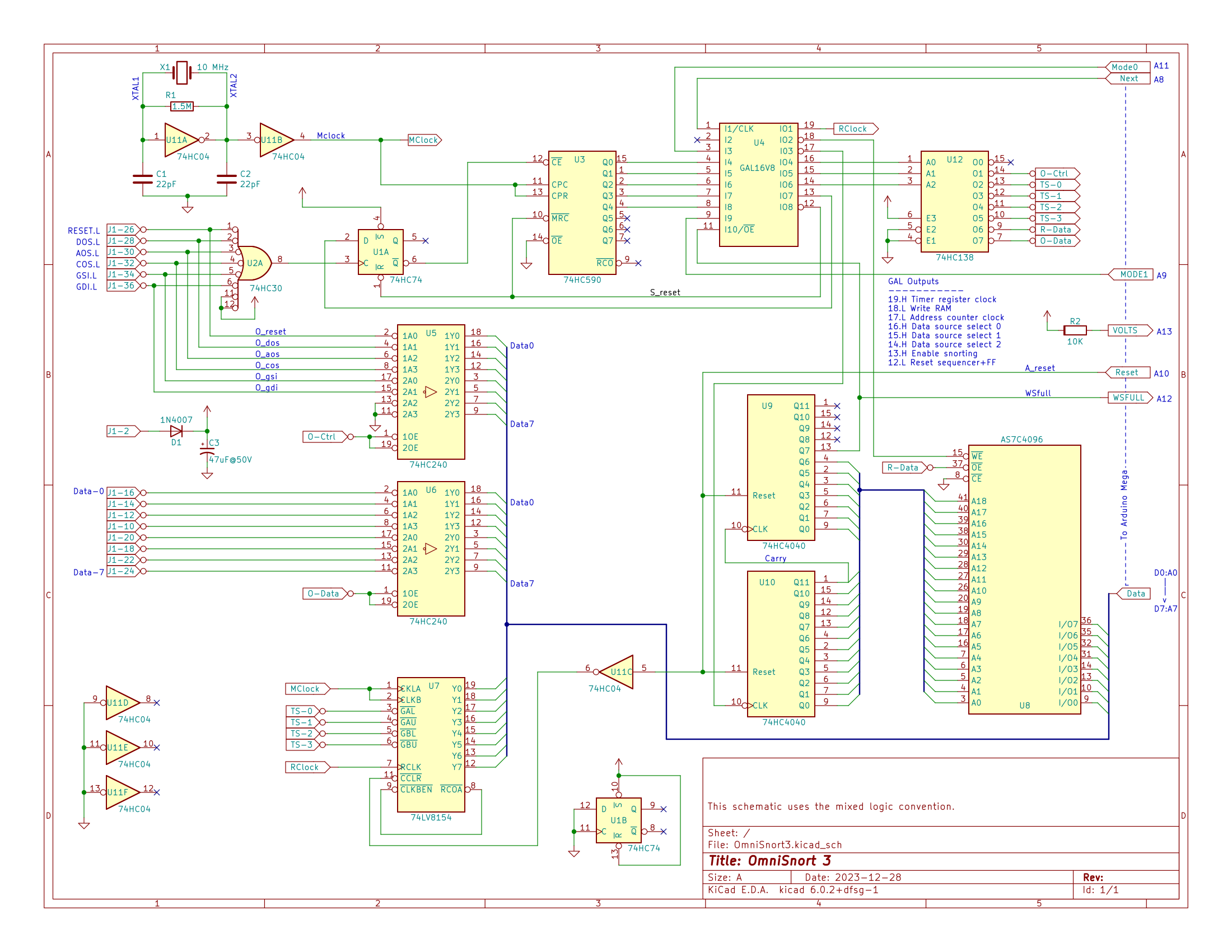
Without further ado here is the OmniSnort 3 schematic:
The Concept
The general idea is that we develop a 32 bit timestamp which advances at 10 MHz aka one count per 100 nS. We have a 512K static RAM chip into which we store data. When an event happens on the Omniport we store six bytes into RAM:
- The Omniport control lines
- The Omniport data lines
- Four bytes of timestamp information
As each event uses up six bytes we thus have room in RAM for 512K / 6 = 87,381 events. That sounds like enough.
How it works
In the upper left corner of the schematic, the crystal and friends generate a 10 MHz master clock "MClock".
At the bottom on the left is a 74LV8154 which is IMHO a fabulous chip which makes the design of OmniSnort *so* much easier. We use this chip to develop the timestamp to associate with Omniport events. It contains two 16-bit counters which have been cascaded to make one 32 bit counter. On command the count can be transferred to a 32 bit register and from there the four bytes of the register can, one at a time, be tri-stated onto the 8-bit output. We clock this chip with our 10 MHz MClock so it will be (2**32) / 10E6 = 427 seconds, or just over seven minutes, before this counter overflows. That also sounds like enough.
Middle-right-low are two 74HC4040 chips, 12-bit ripple counters, which we use to develop the 19 bits of address for the RAM.
Middle-high is a 74HC590 counter and a 16V8 GAL which together implement a really simple state machine.
The RAM, the Mega, and various other chips are connected to an 8-bit data bus, which allows us to get data in and out of RAM.
We want to be able to enable one and only one of seven different data sources onto the data bus, thus the GAL drives U12, a 3-to-8 decoder, which in turn can select one of the seven devices (or none) onto the data bus.
Way over hard-right are the connections to the Arduino Mega. The Mega can access the OmniSnort data bus. The Mega gets the following signals from the OmniSnort board:
- Wsfull: True if our RAM chip has filled up.
- Volts: The +5 from the OmniSnort logic, which in turn is derived from the +5.6 coming in from the Omniport. This allows the Mega to verify that OmniSnort is connected to an MCM computer and to verify that the voltage is sufficient for proper operation.
The Mega sends the following signals to the OmniSnort board:
- Mode0 and Mode 1: Sets the mode of operation.
- Next: When reading snorted data, advances the RAM address counter.
- Reset: Resets both the RAM address counter and the timestamp to zero.
The two mode lines provide for four different modes of operation:
- Snort: Activity on the Omniport is snorted and events are saved into RAM.
- Read: Events saved in RAM can be read into the Mega.
- Pre-write: Gets ready to let the Mega write to the current memory address.
- Write: Data from the Mega is written to the current memory address.
The last two modes are so the Mega can zero RAM prior to snorting so, at read time, it knows when it has reached "end of snorted data".
Operation when Snorting
When snorting, the GAL puts True on the D input of FF U1A. When there is any activity on the Omniport (that is, when any of the control signals goes low) then OR gate U2A clocks FF U1A. That in turn enables the CS/ input of U3 which then starts counting up at 10 MHz. Five of the count bits from U3 are fed to the GAL and this in turn drives the state machine through the non-idle states. We want to store six bytes into RAM and each bytes stored takes 3 states, thus 18 states. For each byte stored the three states are:
- Enable the appropriate data on to the data bus (Omniport control info, Omniport data, timestamp data)
- Write the data to RAM
- Advance the RAM address counter.
The last state of the last byte pulses the S_reset (State machine reset) line which clears FF U1A and which resets the state counter, thus idling the state machine and getting ready for the next Omniport Event.
The logic for the GAL can be found HERE.
The working breadboard of OmniSnort version three looks like this:
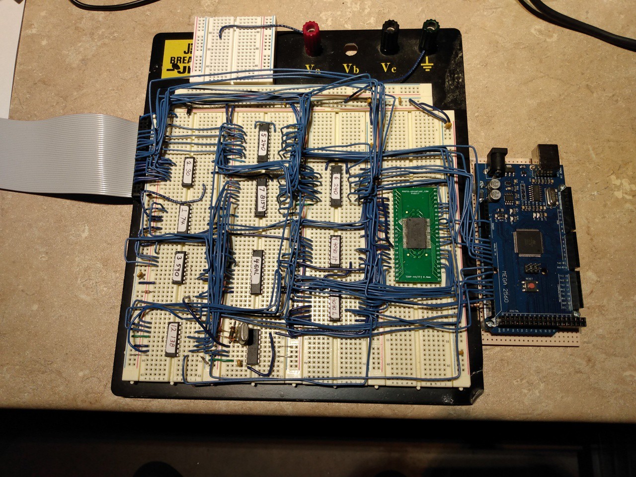
The ribbon cable on the left connects to the Omniport. The RAM chip, being SMT, is up on the green adapter, while the Arduino Mega is on the far right.
With the breadboard version working, I made it into a PCB - sort of an oversize shield for the Arduino - which is now off at JLCPCB for production.
Discussions
Become a Hackaday.io Member
Create an account to leave a comment. Already have an account? Log In.