 Valery
What a drift car is capable of out of the box and how it works, I showed in the first part of my video.
What a drift machine is capable of:
-The charge of the native battery is enough for 10 minutes, after 7 minutes the car just drives without drifting;
- Discrete control;
- Police lighting;
- Drift around;
- Drift eight.
What do I want to do?
-Make front and rear lights;
-Introduce completely your own homemade electronics with proportional steering and gas control;
-Write a program for the typewriter and remote control;
-Put 3S battery;
-Add music to the machine with the ability to switch it from the remote control;
- Make the backlight on the addressable LEDs with the ability to switch it from the remote control;
- Servo steering wheel control;
- And perhaps everything!
Drift car device and prototype
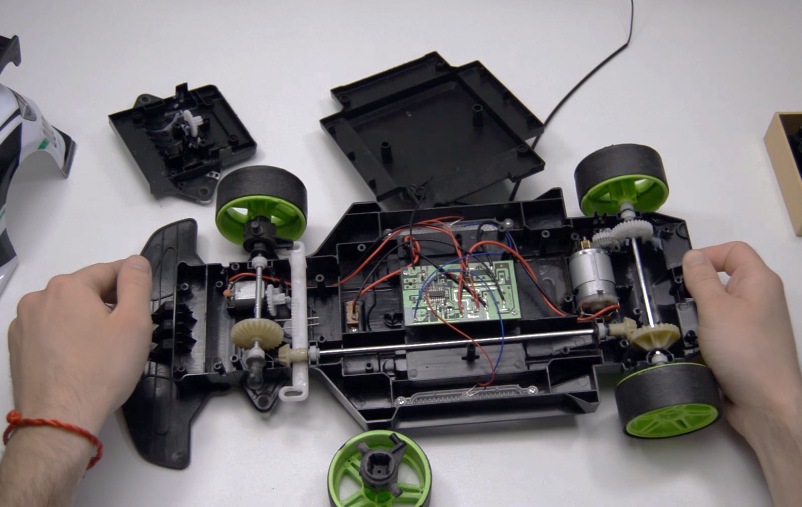
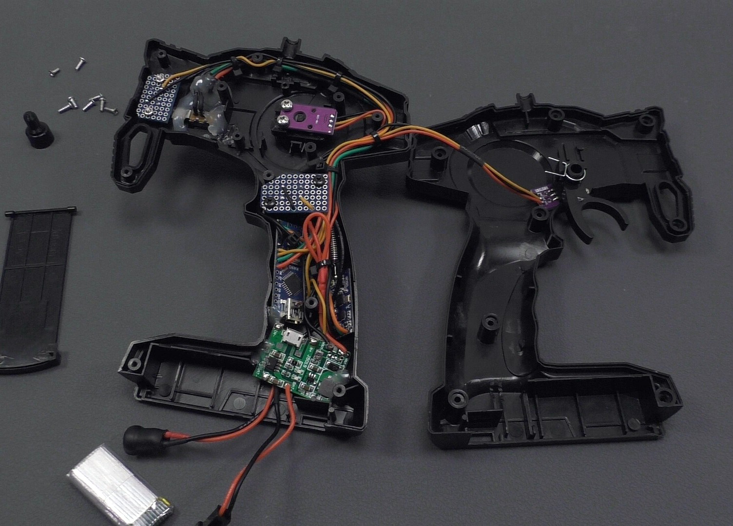
I started reworking the machine by disassembling and studying its device. I took off all the native electronics with the steering mechanism and began to think about how and where to place all the components.
In this project, I have identified two difficult places for rework:
1. Steering.
- I have a rough idea of how the steering should work on a servo, but how to place it and will the small servo have enough power? For me, these were the main questions and fears.
2. Alteration of the remote control.
- Since the native equipment of the drift car has discrete control, it will be difficult, according to my feelings, to convert it to proportional control, because you need to somehow build variable resistors into the remote control, but what if it doesn’t work out? Well, as they say, the eyes are afraid, but the hands do!
It is very important in projects to find difficult places or things that cause the most problems, these things need to be done first and after solving all the difficult tasks, do everything else. It would be very stupid to abandon the project at an almost finished stage, when all the simplest things have already been done, but you cannot complete the project because of 2 difficult tasks that you decided to postpone. As a result, you get an abandoned project that needs to be redone or finalized.
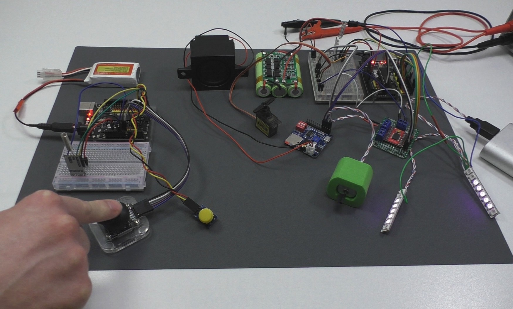
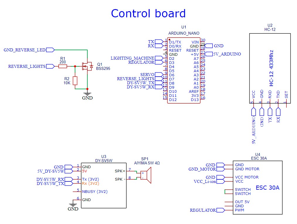
After studying the device, I had several options for the location of the components, first of all, I tested the servo and decided on its power. I thought over the steering mechanism, the location of the servo drive and the device of the control panel. In order to finally decide on the device of the machine and the remote control, then it is necessary to prepare the electronics. I wrote a program in the Arduino IDE, assembled and debugged the prototype, after that I made a circuit diagram of the electronics of the drift car and the remote control.
Printed circuit boards for electronics
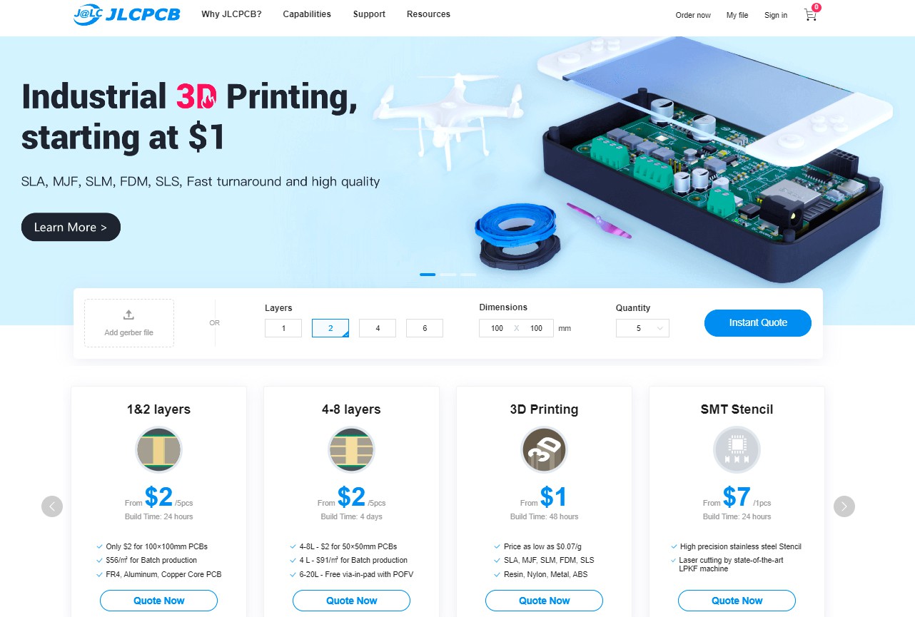
In order not to suffer like me with the manufacture of boards on a breadboard, I recommend ordering the manufacture of printed circuit boards from https://jlcpcb.com/. This is the largest enterprise for the production of printed circuit boards of industrial quality, of any complexity, of any size. For just $2 plus shipping, JLC PCB will make you five 2-layer 100x100mm PCBs, or five 4-layer 50x50mm PCBs! JLC PCB can not only manufacture boards, but also assemble them on their surface mount equipment.
To place an order, you need to upload an archive with gerber files to the site, in the order itself you can configure the necessary parameters, such as the color of the mask, the thickness of the textolite, copper and order the assembly of boards, also JLC PCB is engaged in 3D printing, making stencils for SMT mounting and all this makes in the shortest possible time and with the best quality, so I recommend them.
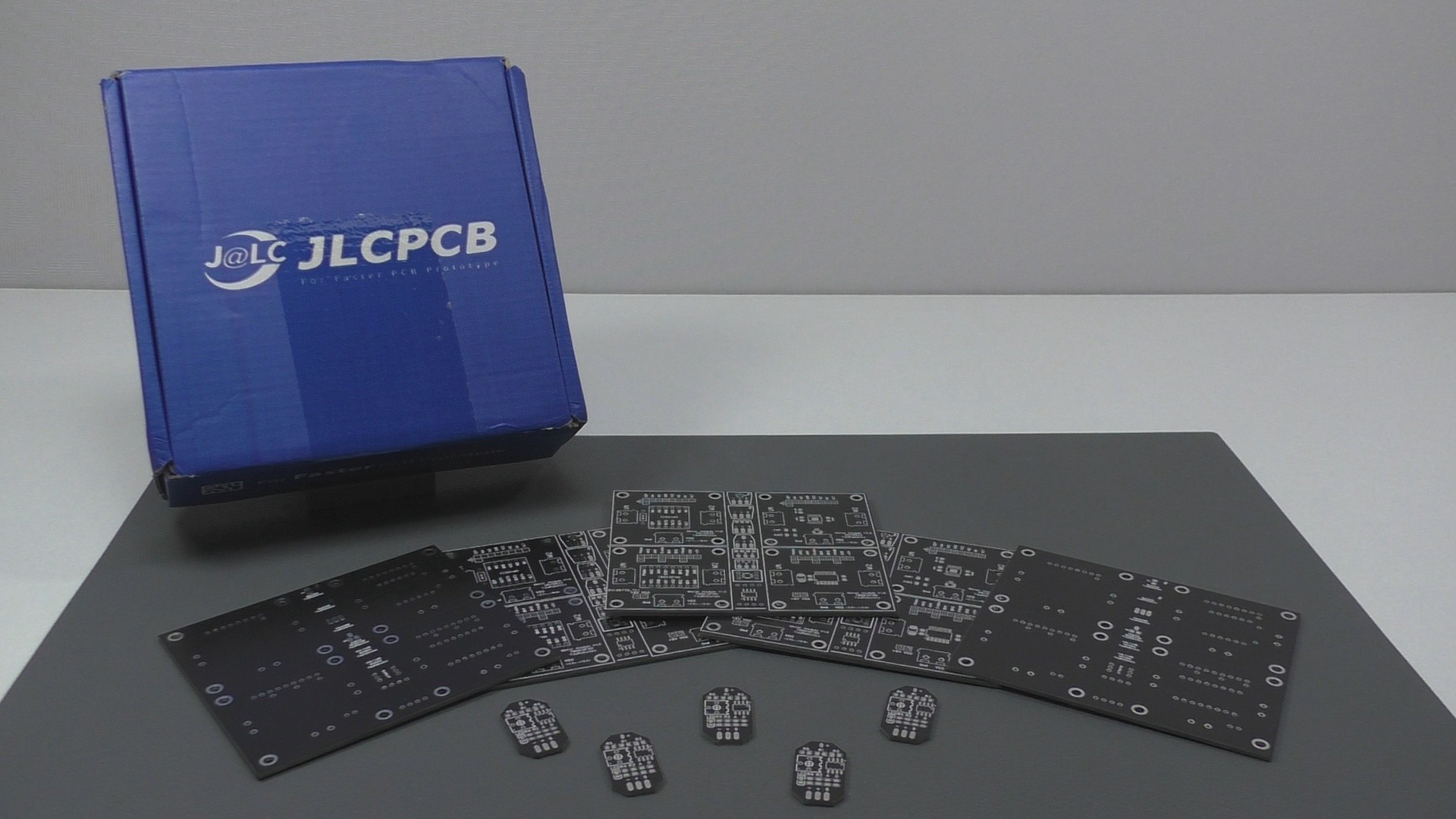
Printed circuit boards for electronics
The following printed circuit boards are required:
- Power board - 1 piece;
- Control board - 1 piece;
- Board for connecting LEDs - 2 pieces;
- Printed circuit boards for buttons in the control panel.
I made all the listed printed circuit boards from breadboards, soldering the tracks with solder. This method of manufacturing printed circuit boards is not always suitable and it is quite difficult to think through the passage of all the tracks, and the soldering process itself is complicated if you want to do it neatly and beautifully. Therefore, I recommend ordering printed circuit boards in production, do not suffer, do not repeat my mistakes :)
You can find Gerber files for ordering printed circuit boards at https://github.com/Vallerik/DriftCar.
Everything is clear with printed circuit boards, it remains to deal with the steering mechanism, battery and the location of all electronics.
The device of the new steering mechanism
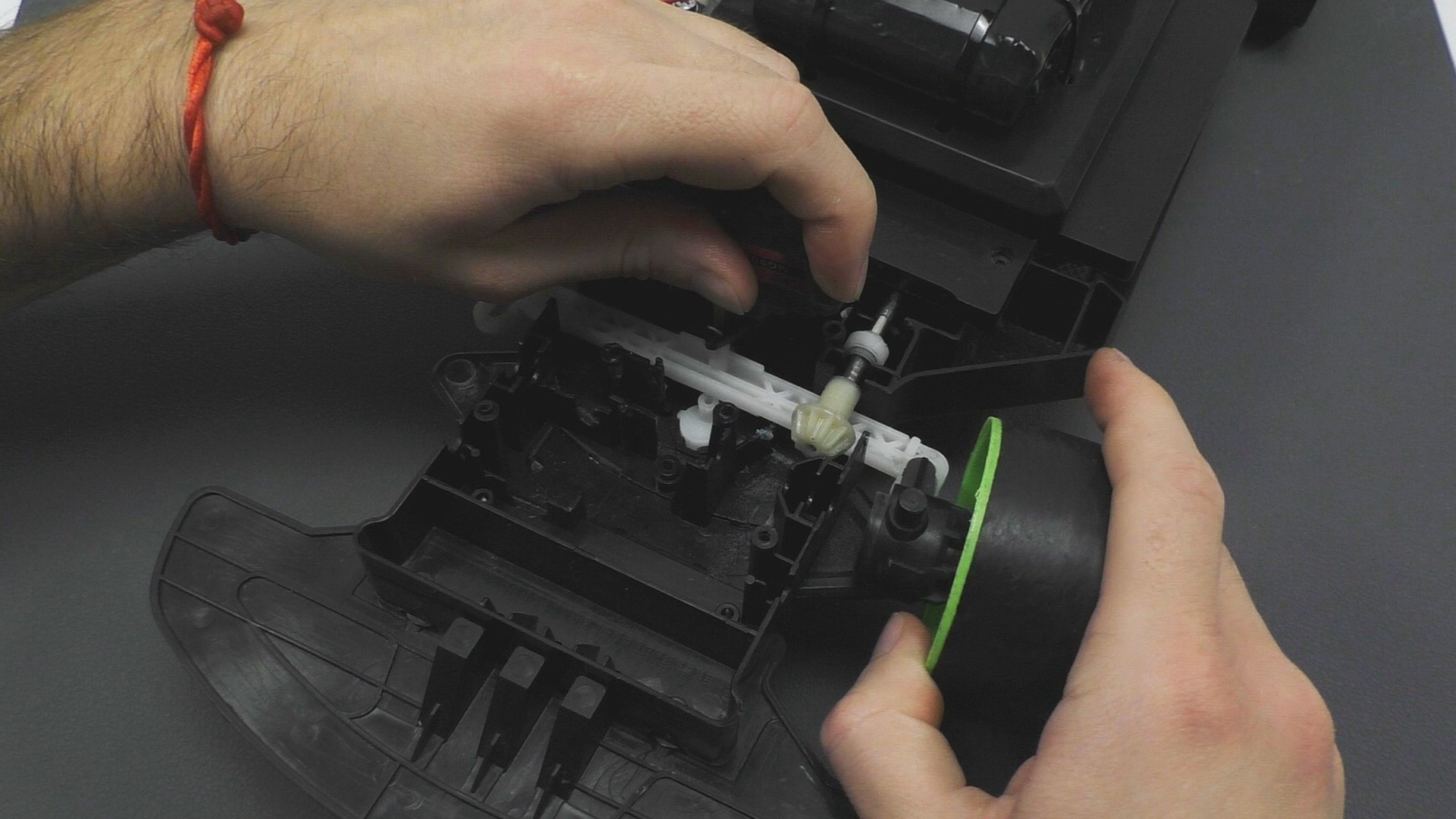
The ideal place to fix the servo coincides with the plastic stand in the case. The second ear of the servo is already screwed to the brass stand in place. In the central position of the servo, a rocker with a drilled groove is screwed.
A curved pin glued into the steering rack is inserted into this groove. The pin is made from the original spring of the steering gear, teeth for the gear were bitten off from the rack itself.
And the only important point, you need to install the rocker in the central position of the servo (90°) and the servo itself is screwed through a spacer printed on a 3D printer. The servo drive, turning the rocker, moves the pin along the groove, thereby setting the steering rack in motion. The mechanism works perfectly, there is enough servo power, there is no jamming, and I was even surprised how well the arrangement of the components coincided.
Battery assembly
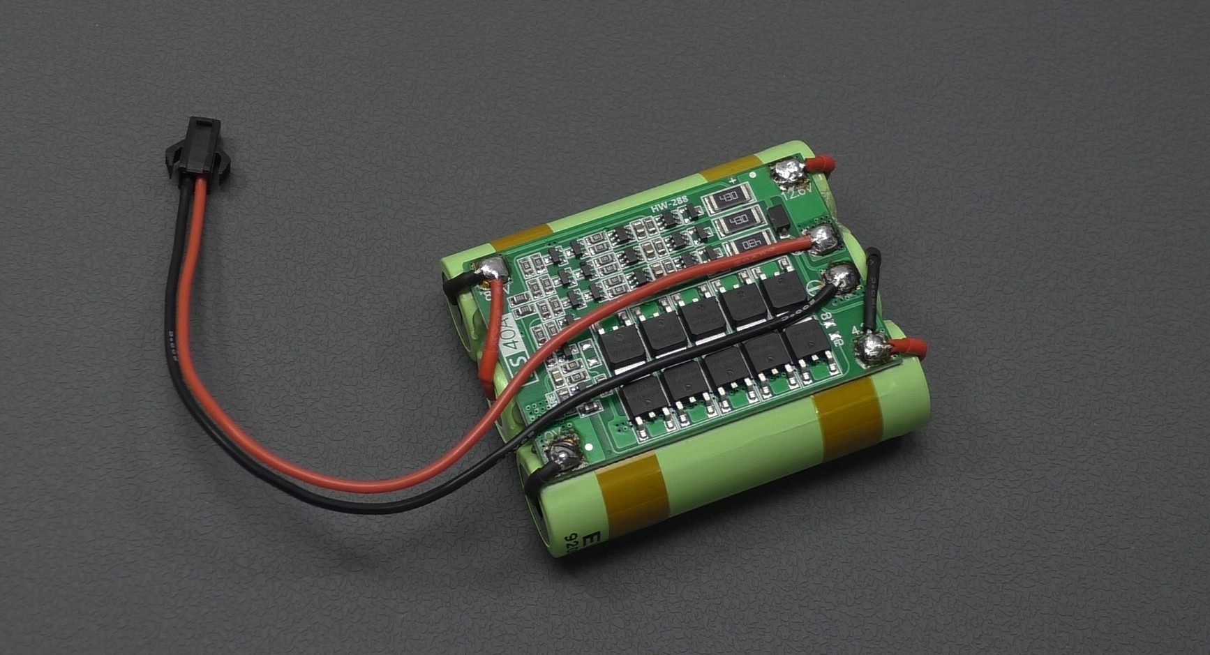
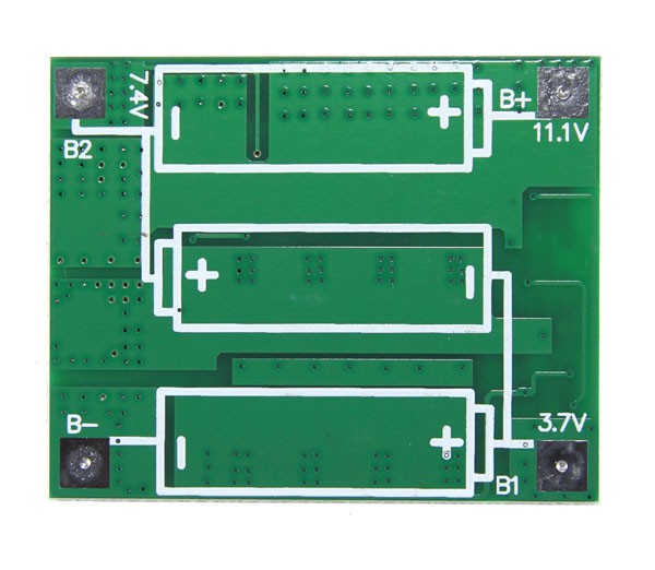
There is nothing complicated in assembling the battery, I think everything is clear just from the photo, the wires of each 18650 can are soldered to the corresponding BMS contact of the board. To connect the battery, a wire with a JST SM 2.54 2P male connector is soldered to the BMS.
Headlights
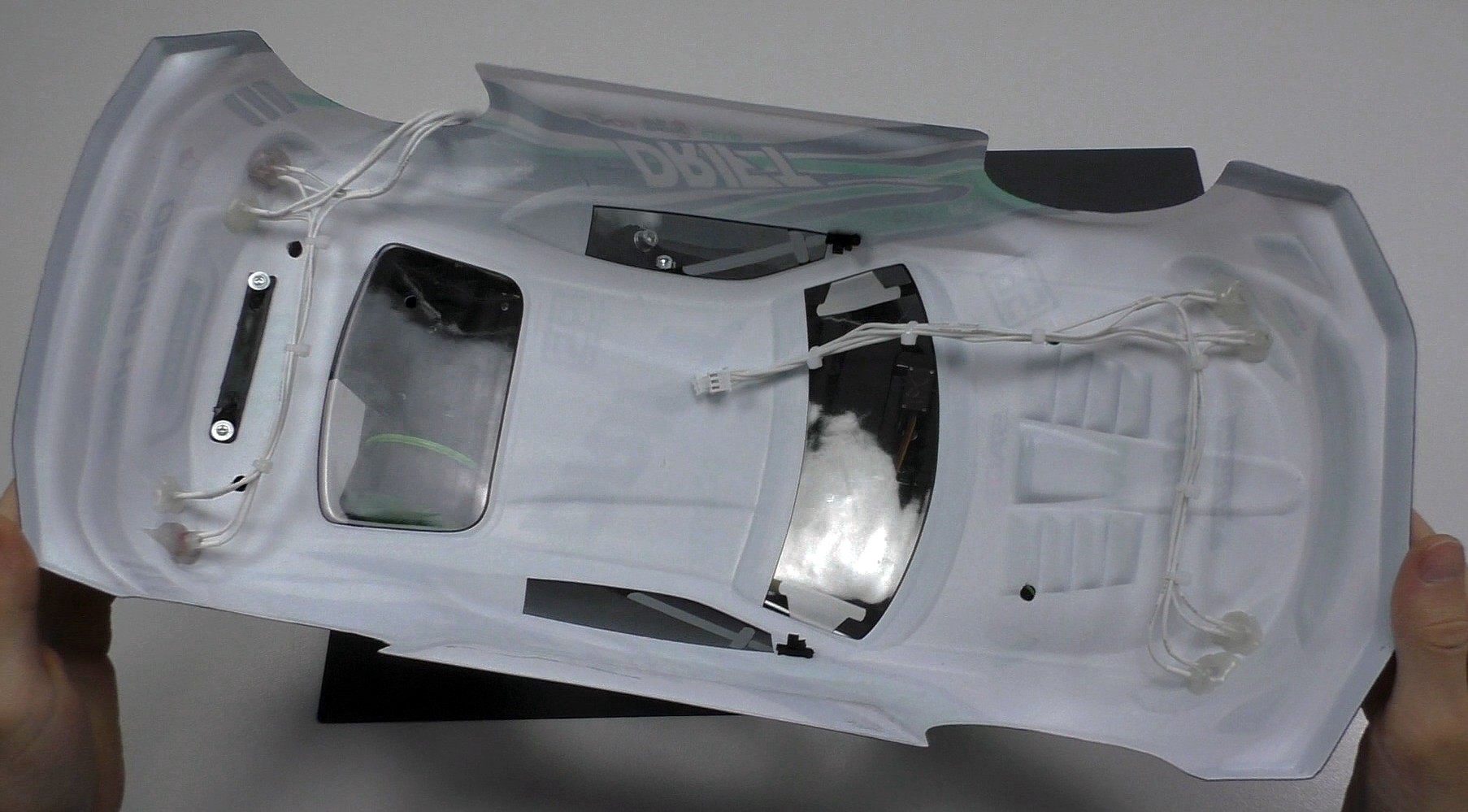
Holes are drilled on the body in the center of all the painted headlights and LEDs are glued with hot glue. Beforehand, it is necessary to solder the wires to the LEDs according to the scheme.
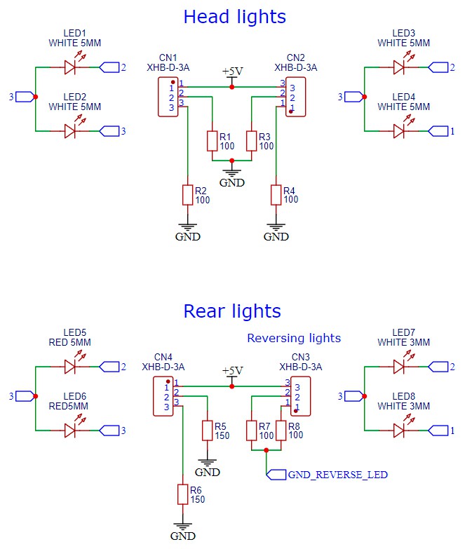
The headlights are made from 3 and 5mm white LEDs. Reversing lights made of white 3mm LEDs. The oversized red headlights are made from matte red 5mm LEDs.
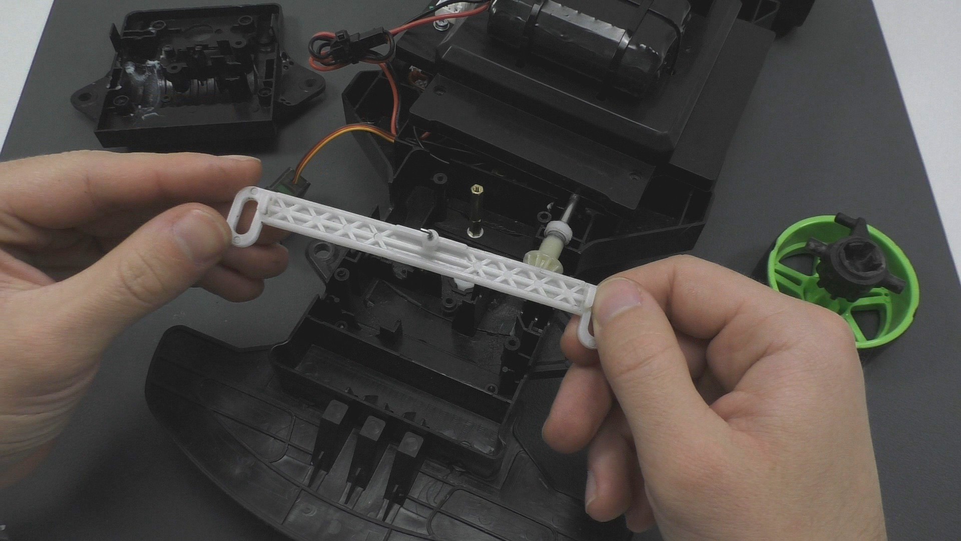
The wires from the headlights will be connected to the XH 2.54 3P connectors (Each wire is connected according to its color mark), printed circuit boards with these connectors are screwed to the side of the central cover of the machine. Racks with a speaker are screwed to the same cover and the battery is attached to plastic ties.
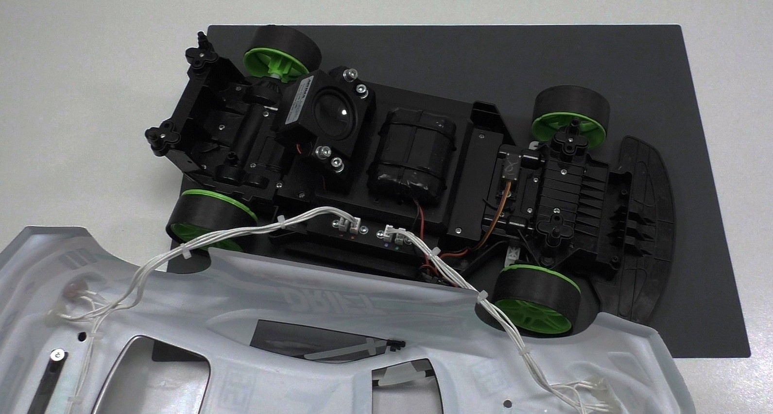
Location of electronics
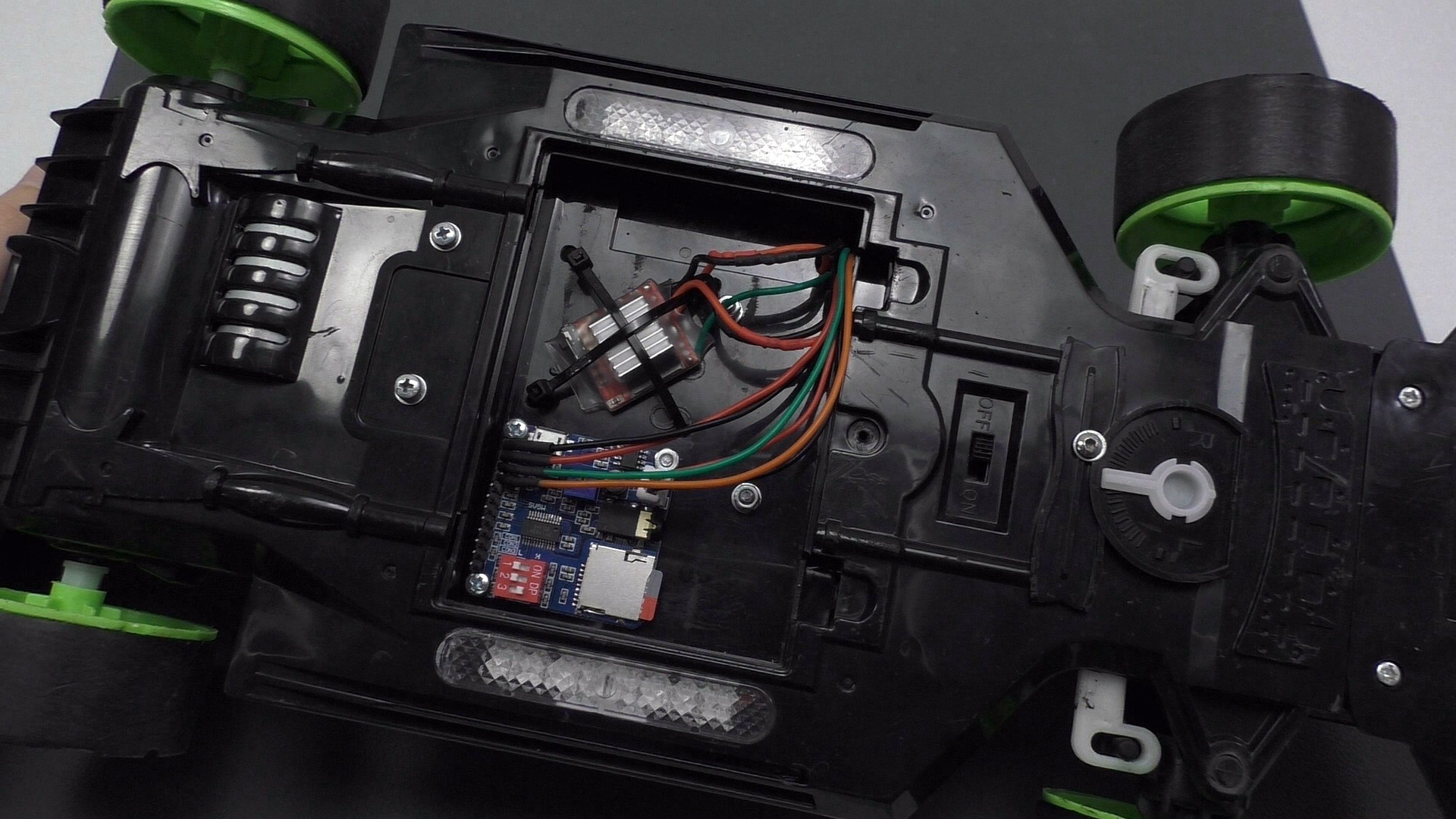
In the compartment for the old battery, I screwed the board from the player onto the plastic racks, and fastened the speed controller to the plastic ties.
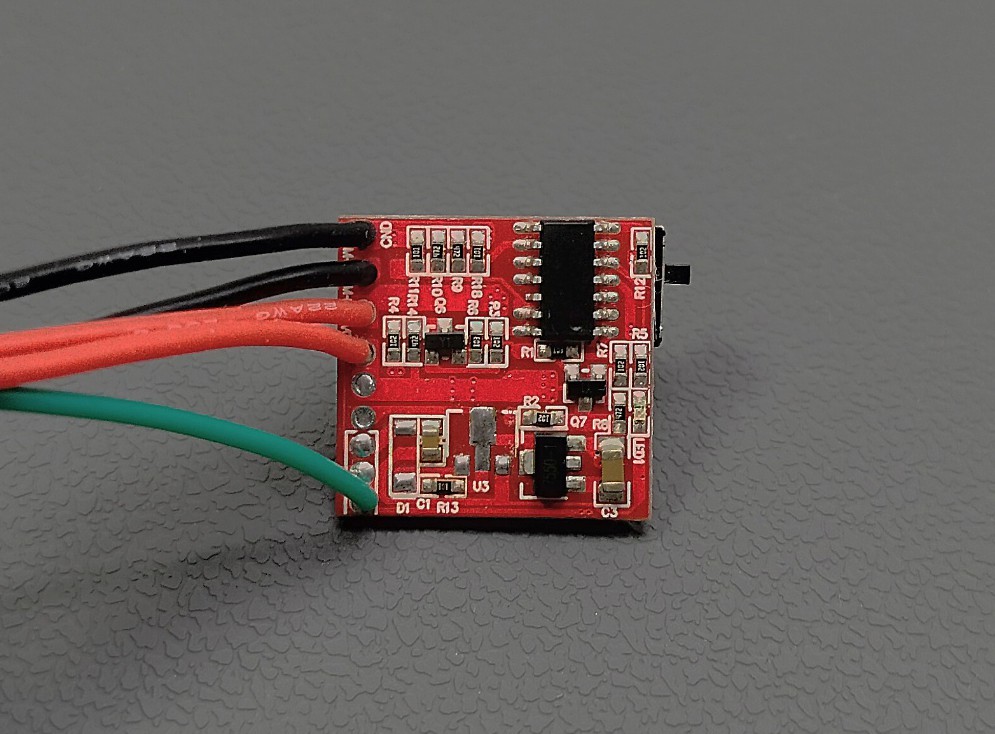
By the way, this regulator needs to be improved to prevent its heating when powered by a 3S battery. The fact is that this speed controller, according to the seller, only supports a 2S battery. When a 3S battery is connected, the regulator also works, but the diode and transistor start to heat up, I dropped these components, the printed circuit board stopped heating and the regulator works properly. All components on the PCB support voltages above 12 volts, so everything is fine.
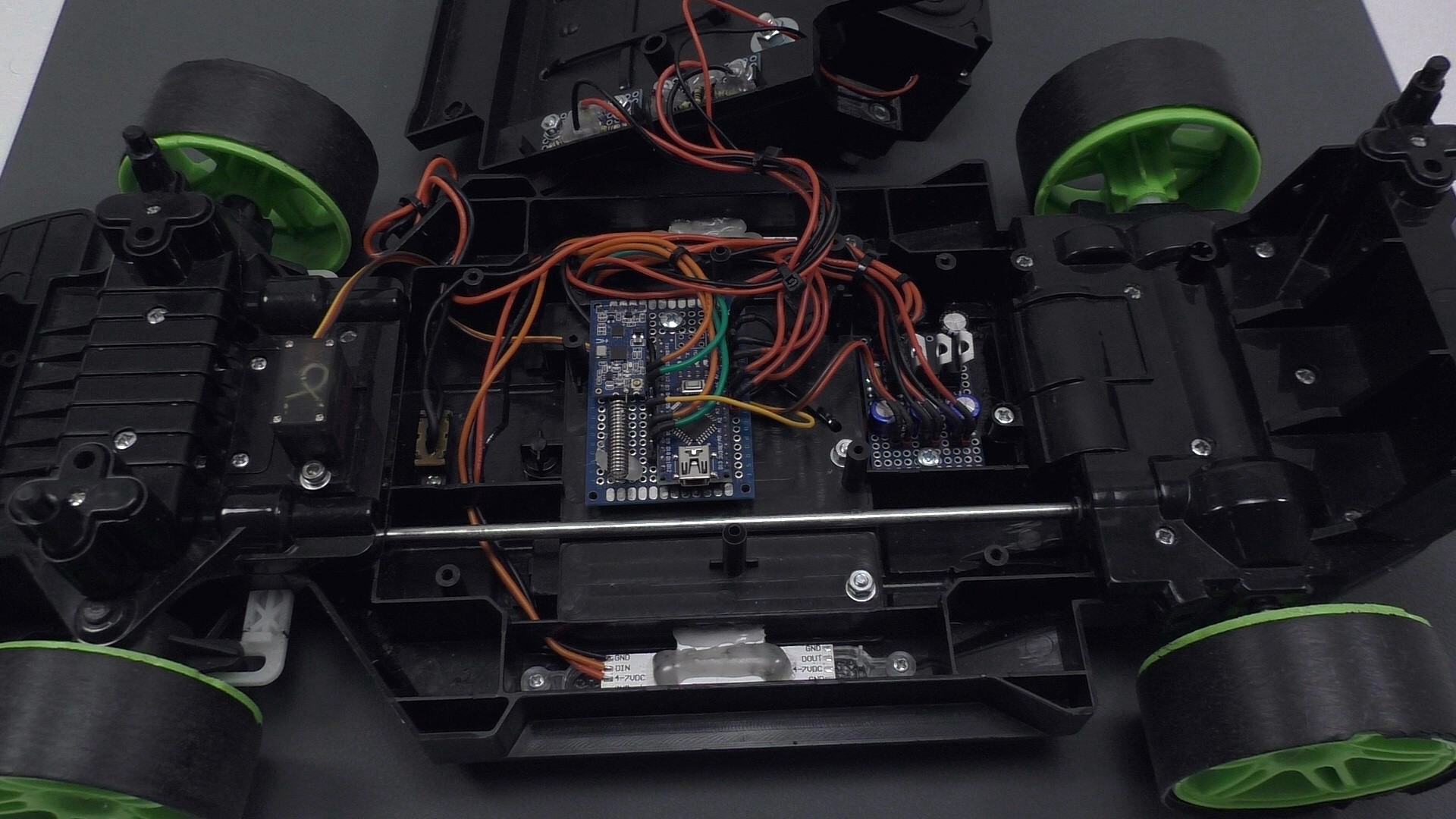
Under the central cover in the middle, there is a board with an Arduino Nano, after which a power board is installed and panels with addressable LEDs are glued on the sides. All electronics are connected according to the specified scheme.
The native switch in the front is used to turn off the power, some holes were also made in the case for wires, well, the whole bunch of wires, if possible, was fastened with plastic ties.
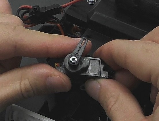
Alteration of the control panel
To remake the control panel, the first thing I thought about was how to install the CJMCU-103 module. To do this, I printed on a 3D printer a special mount and pins for turning the CJMCU-103, these pins are glued into the trigger and steering shaft. The first CJMCU-103 steering wheel module is screwed to the mount and the second CJMCU-103 is screwed to the console cover. All other electronics are connected according to the attached circuit diagram.
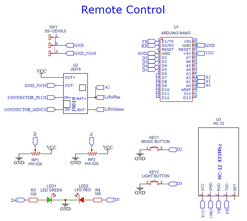
Also, for the remote control, two printed circuit boards were cut out for the buttons, a two-color LED was glued in, a switch and a resistor for setting the charging current was changed on the green charging module, for a li-po battery with a capacity of 400 mA, I set the charging current to 300 mA. Charging takes place with a USB cable that plugs into a 5.5x2.1 mm jack. There is nothing else special in the remote control, and well, I also changed my native antenna to a small one printed on a 3D printer. In general, the remote turned out great!
Project results
Now let me summarize, has the car started to drift better? The result, of course, was not the same as I expected, but the car became more cheerful to drive from a 3S battery, due to the proportional control, the car became better controlled and, of course, it is better to look with headlights and RGB backlight. A loud speaker makes the bass vibrate and play the whole body, these are indescribable sensations of the joy of a working project. My main goal is accomplished, to make a musical drift car with my homemade electronics. From the remote control, I can turn on, switch music and backlight, the backlight still has 7 modes of operation, well, in general, I'm exhausted, but satisfied. I will not say that I am an expert in this matter, I just set a goal for myself and achieved it. And in this article, I shared my project and experience, at the end of the project, I want to warn you that developing your own electronics and modifying such toys is not as easy as it seems. If you want to repeat the project after me or do something similar, I would advise you to install ready-made electronics, a receiver, a speed controller, a purchased battery with equipment, it will come out easier, cheaper and faster. Well, that’s all for me, don’t scold me much for my first article, I’ll try to accept criticism with understanding, thank you all for reading or watching my videos. Bye bye!