 Lars Lund Hansen
Background
I followed the very good instructions by @Anton for both the first “8mm Film Scanner”, and for the V2 version with improvements made to the base unit mount plate and film plate.
I 3D printed all parts in PLA. The electronics hardware is Raspberry Pi 4, a Pi Camera 2 and a home-made PCB compatible with Anton’s v1 schematic. All other components are as listed by Anton - apart from those used for the control panel and the case. My scanner device is now just a bare version without a case and with no control buttons apart from the power button.
When I first tried to use the scanner with the original Regular 8 software (pi4_R8_scanner.py) and a mock up control button panel, I experienced that the scanning stopped on some sections of my 60 years old Regular 8mm films. I then adjusted some parameters in the code, added debug and extra views of the sprocket hole area, and tried again (and again ...).
The problems I had were related to the automatic location of the sprocket holes in the film. The control of the process using the push buttons were also not easy for me.
I came to the conclusion that for me it would be better, to have a program with a GUI to control and monitor the scan and crop process.
How my version of the scanner software works.
As Anton I chose to use python as programming language. The basic algorithm using OpenCV is still like Anton coded it. For the GUI I chose PyQt5. For interface to the Pi Camera I chose the new picamera2 module. My python code can be found on github.
Here I will explain about 8mm film and how the scanning process works. I must note that I only have worked with Regular 8 film, but I hope that the settings.ini can be adjusted for use with Super 8 film.
On an 8 mm film the individual frames are positioned with a fixed distance to the sprocket holes. A frame sits right in the middle between two holes.
Here is a typical frame scan as seen by my film scanner camera.
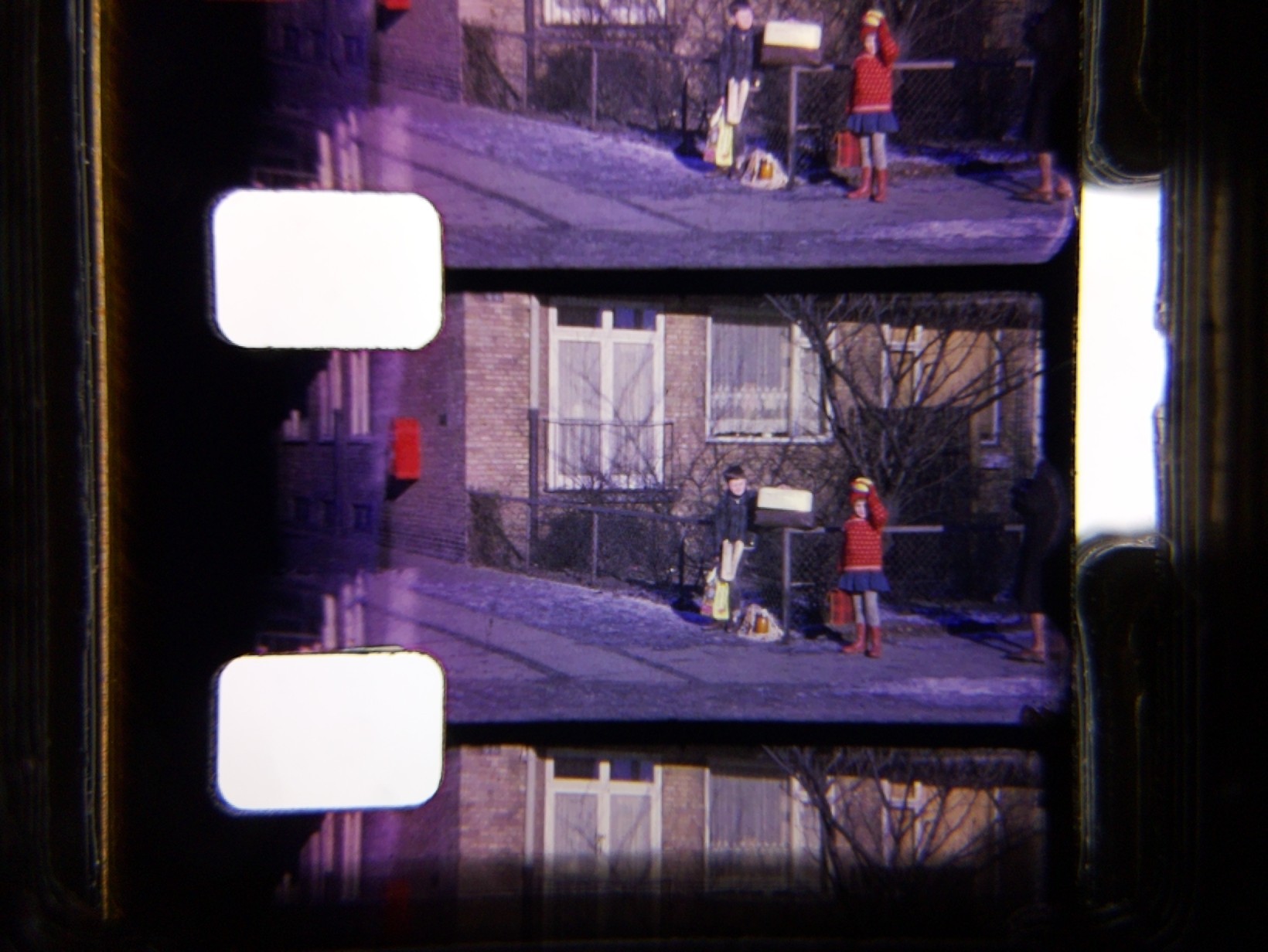
This is the closest view of the film I can get with my setup. I have set the camera resolution to 1640x1232. The resulting size of a cropped film frame is then about 800x570 pixels.
This is OK for my purpose.
The software tries to position the frame to be scanned centred in the camera view in order to get the best quality. This is done by tracking the position of the upper sprocket hole and moving the film forward or backward. Functionality from the software module OpenCV is used to locate the exact position of the hole.
When the images are scanned the stepper motor moves the film forward one frame at a time.
The number of steps needed for forwarding one frame is approximately 80 microsteps (Regular 8) when the DRV8825 is set to 8 microsteps/step (M0=1, M1=1, M2=0) as in Anton’s software.
When moving many frames forward a small adjustment is needed from time to time.
Finding the position of the sprocket hole
The OpenCV function cv2.findContours is used to find the hole position. Input is an 8-bit image with only two colours black and white. The output is a list of detected contours in the image stored as a vector of points. Another function cv2.contourArea is used to get the pixel area of the located contours. If a contour with an area big enough to be a sprocket hole is found, its center coordinates can be found using the cv2.moments function.
Instead of using the whole picture in this process, the software uses a cropped part of the picture, that is supposed to contain the hole, and converts this to a down sized two-colour image. This saves time, but complicates the position calculation a little.
The conversion of the sprocket hole crop, to a two-colour image is done by the cv2.threshold function. The function is fed an 8-bit monochrome version of the image and an intensity threshold value. Depending of the film colouration around the hole in the monochrome image, this threshold value is important to set right. The background colour seen...
Read more »
 Jana Marie
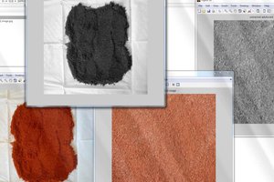
 G.Vignesh
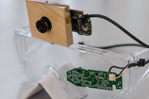
 John Evans
 Eugene