wryan67
The system was designed around, and tested using a "Tail Twister" Model T2X - Rotator. A link to the owners manual is in the links section. My father, Dr. Bill Ryan also helped with the initial concept and design.
Some of the basic components include standard relays, an A2D converter, and an op-amp. The basic idea is that the op-amp will levelize the voltage coming in from the rotor's aspect indicator, and then the output of the op-amp will be fed into the A2D converter where the Raspberry Pi will read it and display on the screen the position of the antenna.

Above is an example of a 500 Ω aspect indicator and also a scope image of what the voltage looks like, both directly coming off of the aspect indicator and after it is fed through the op-amp. When the motor is running there is a lot of 60hz interference, which is being captured on the yellow channel. The voltage is fed through an op-amp which filters out the interference and leaves you with a steady voltage, as seen on the blue channel.
The user can then input the degrees he wishes to move the antenna to, or using the touchscreen, he can press one of the preset buttons to move to a cardinal position. VNC can also be used to control the system remotely.
Using a set of relays, the Raspberry Pi can turn the rotor's brake on and off, and then activate the motor in the proper direction in order to move the antenna to the desired position.
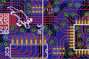
Again, thank you PCBWay.com! After I uploaded my Gerber files, I found a mistake on version v1.00 and their support staff was able to stop the production, which allowed me to upload new, v1.01 files and then production was rescheduled. The support staff was kind and courteous throughout the entire process. It took about a week from between when I opened the request to when I receive the boards. The boards look and feel amazing! This was my very first time ever to upload a schematic or Gerber files to have a PCB may by professionals. It sure was a great experience and I'll use PCBWay.com in the future for sure. This time I elected to solder the parts on myself because there are two tolerant sensitive parts and since I'm new, I wasn't ready to learn how to specify parts, much less the tolerance required for said parts. Maybe next time.
Photo Galleries:
- [Rotor Gallery v0.10] -- Original build
- [Rotor Gallery v0.20] -- Home-made circuit board
- [Rotor Gallery v1.01] -- Thank you PCBWay.com!!!
30 second video: [video link]
Parts list: [click here]
Also, a huge thank you to Elliot Williams for his article on low pass filters which helped me greatly understand how they work and which one I needed to use in this project.
Low Pass Filter: [click here]
 RodolpheH
 danielmcgraw
 Patrick Van Oosterwijck