 Raphael Valceschini
Principle of operation
The principle of operation is relatively simple: the GPS data are collected thanks to an ultra-low power GNSS receiver from u-blox and a satellite communication module from Astrocast is used to transmit the data to the cloud.
The GNSS receiver is a MAX-M10S from u-blox. It does not output a so called "3D fix" with lat./lon., but a raw sample of data that we need to upload to a server that will return the 3D location of the tracker.
The following schematic summarizes well the overall acquisition process:
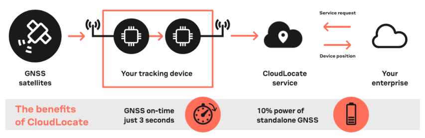
Follow this link if you want to learn more on the "CloudLocate" service from u-blox.
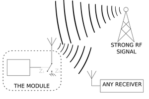
So how do we transmit our raw sample of data to the server ? Well, it's now that we have to give some more details on the satellite communication module from Astrocast: the Astronode S.
The Astronode S is a low power bi-directional satellite communication module which uses the L-band frequency band to communicate with the satellites. Once the raw GPS sample is acquired, the tracker will place it in the message queue of the Astronode S and the module will automatically look for a satellite from the Astrocast constellation. When a satellite is in view, the module will transmit the data that will then appear on the Astrocast portal.
The following schematic summarizes the overall data upload process:
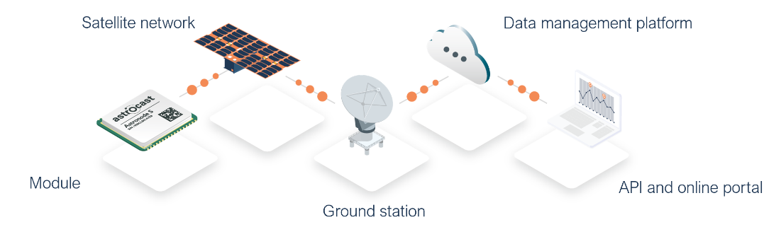
Follow this link if you want to learn more on the service from Astrocast.
In the schematics of the tracker, you will see that the Astronode S and GNSS receiver share the same patch antenna as they are working in the same frequency range (1.5 - 1.6 GHz). The RF switch that has been selected is a GRF6011 from Guerrilla RF. Its fail safe feature enables a good low power solution: when the RF switch is not powered, one of the two RF path will present low insertion losses (<0.4 dB). When the switch is powered, the second RF path will instead go in a low insertion loss state as illustrated below:
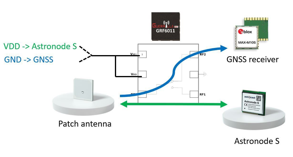
This solution allows to keep the GNSS RF path active when the RF switch is turned off. When the Astronode S wants to use the antenna, its "ANTN_USE" pin of the module will power up the RF switch and connect the Astronode S to the antenna.
Tracker "fact sheet"
The main features of the tracker are listed below:
- GNSS "snapshot" mode (u-blox MEAS20 messages for M10 receivers - data will be processed on CloudLocate service.
- Single shared antenna for satellite communication AND GNSS acquisition.
- Remotely configurable thanks to satellite downlink (user can set the tracker configuration such as acquisition rates).
- Real-time scheduler (GNSS/sensors acquisition, generate status reports, etc.).
Some key technical aspects are listed below:
- Framework: Arduino core for SAMD21.
- GNSS module: MAX-M10S from u-blox (L1 band: 1.575 GHz).
- Communication module: Astronode S from Astrocast
- Downlink frequency: 1525-1559 MHz
- Uplink frequency: 1626.6-1660.5 MHz
- RF switch: GRF6011 from Guerrilla RF
- PCB substrate: FR4, 4 layers
- Connectors:
- 2 pin JST connector for wired battery.
- USB interface for programming.
Some facts on latency and acquisition rates:
- GPS acquisition rate: from 1 sample per day up to 1 sample per hour.
- Message end-to-end latency: a few hours (depends on the location of the tracker).
Low power - Yes, but how much ?
Here is a good place where to provide some power consumption profiles for the main components of the tracker. But first, we need a bit more theory...
What will influence the power consumption ?
Well... it depends... A few of the factors that will have an influence are listed below:
- Data transmission frequency: the higher the acquisition rate is, the longer the GNSS will stay ON and the larger the amount of data to transmit will be.
- Operating temperature: higher temperature will increase the power consumption of all the components on the tracker.
- Battery capacity: the bigger, the longer the tracker will survive...
- Network connectivity: more specifically for the satellite...
 Julien
 Brian Wyld
 Artem Kashkanov