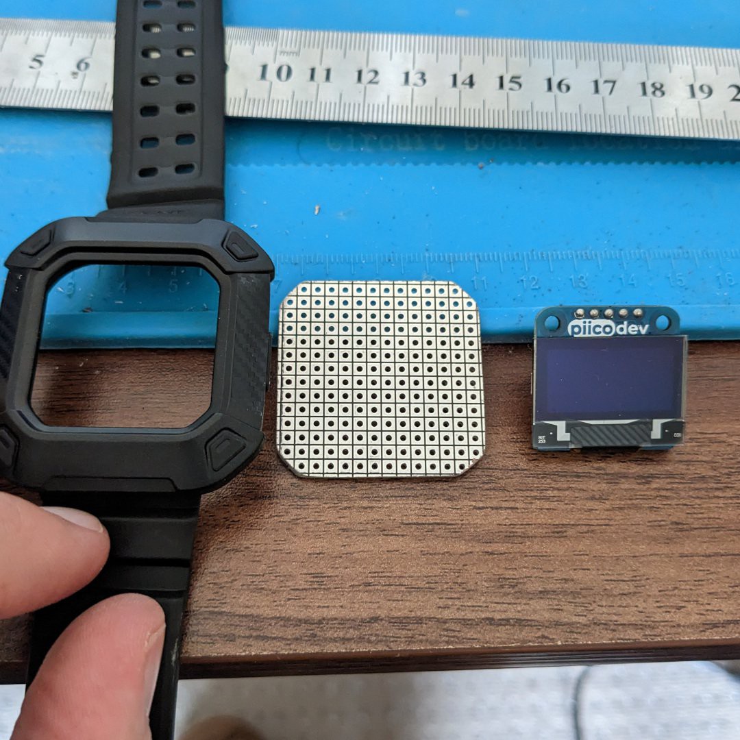
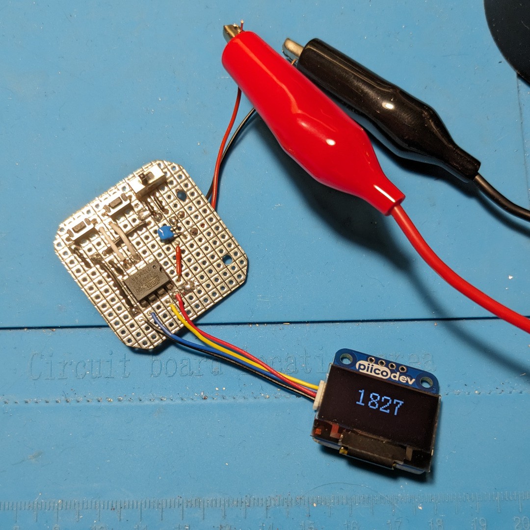
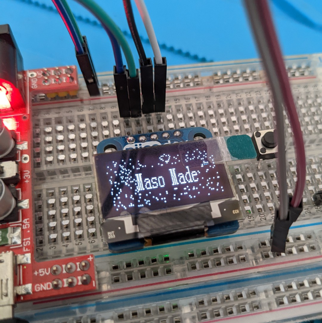
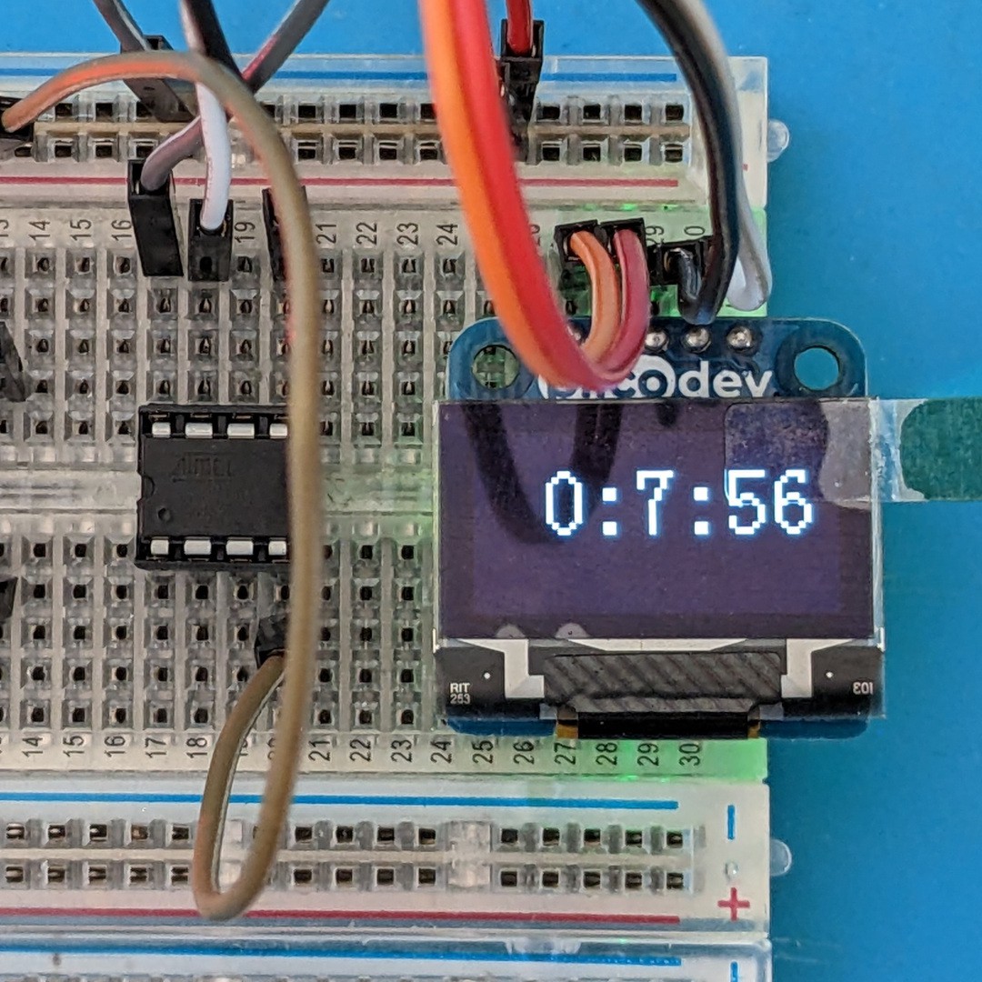
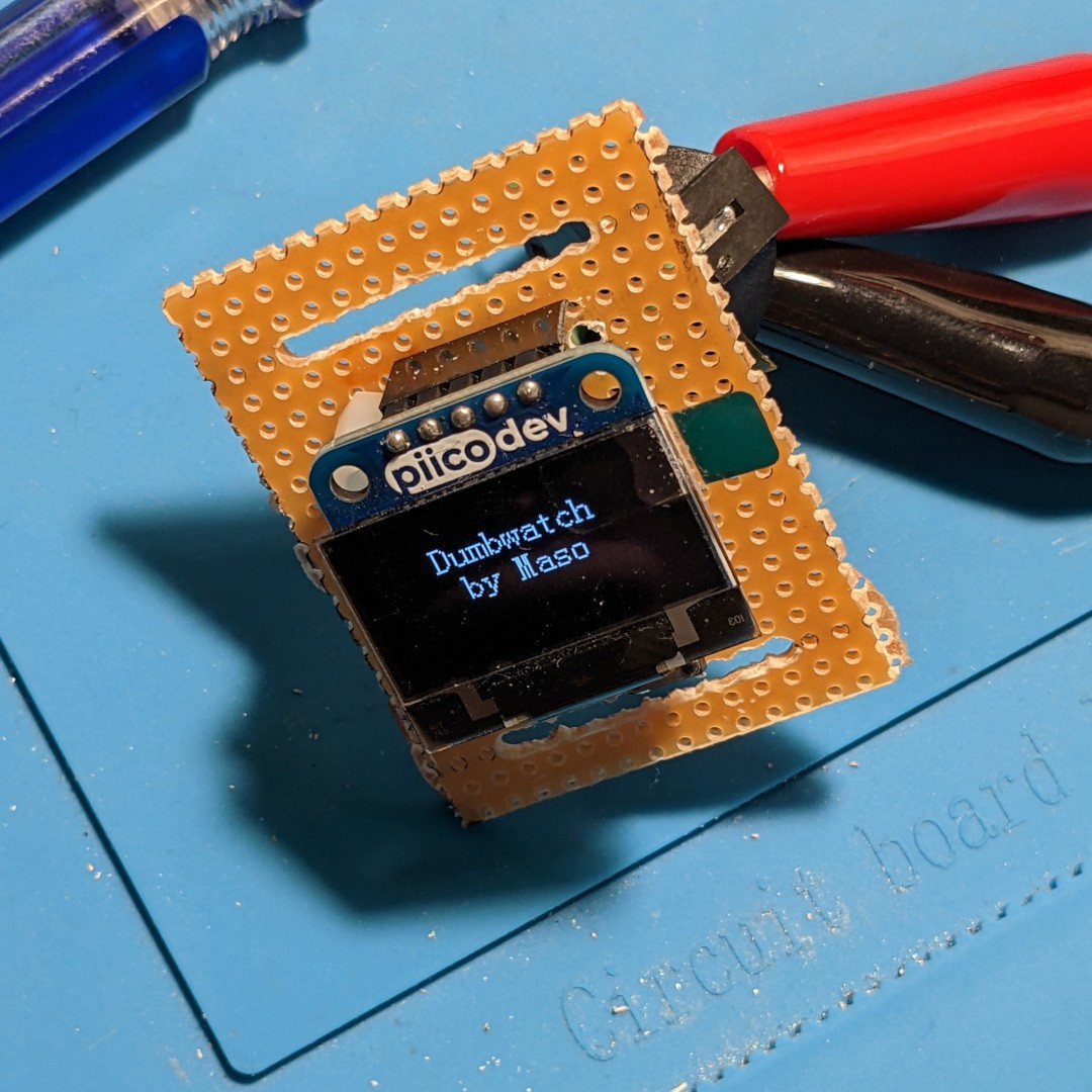
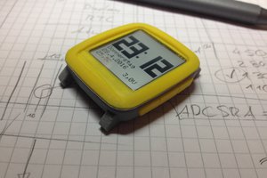
Close
0%
0%

Dumbwatch V2

Minimal ATtiny85-based watch with OLED Display

Similar projects worth following
After taking stock of the lessons learnt from the ATmega based V1 I decided to switch over to the ubiquitous ATtiny85 for an even more minimal wearable.

This ATtiny85 based timepiece is an exercise in making the most minimally viable (not accurate) timepiece possible. Building on the I2C OLED/MCU combo of the previous version, this upgrade makes the important distinction of being functionally wearable with minimal fuss.

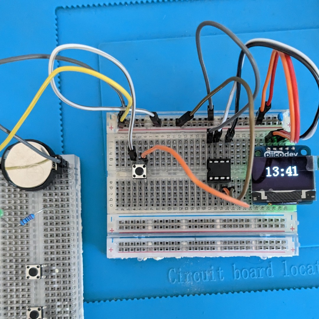
In it's current form, the watch time is manually set with a single tactile button located just below the display.

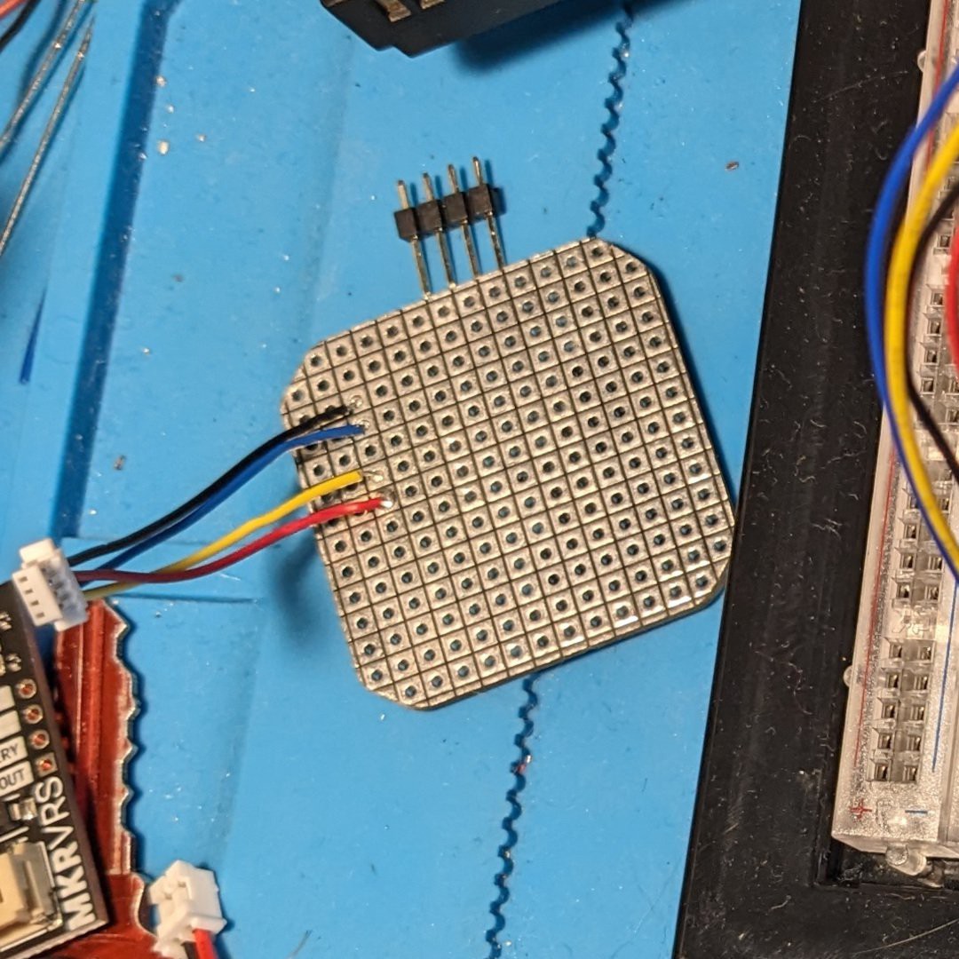
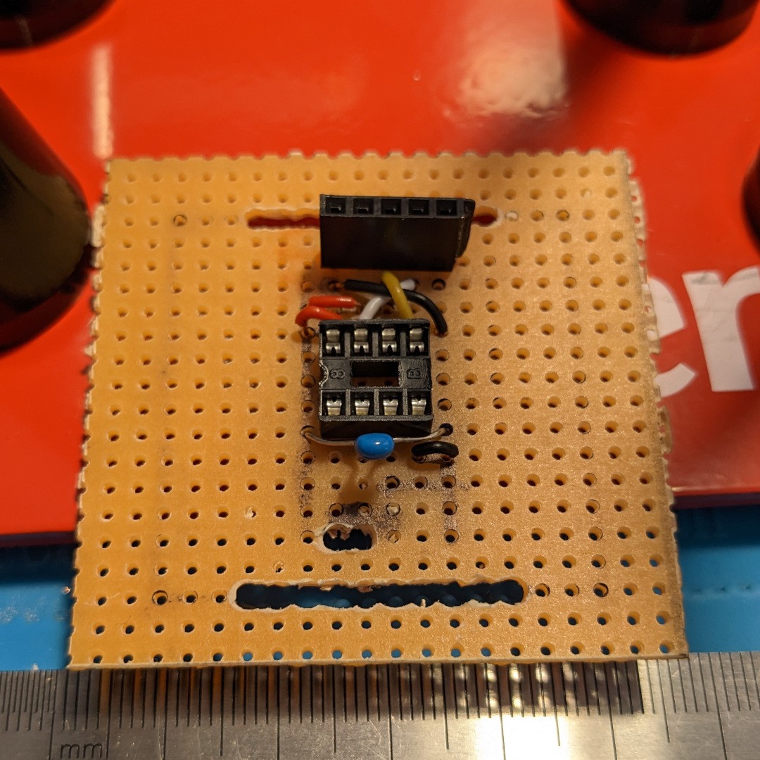
This watch is built with the intention of being a base to iterate new revisions as easily as possible. Hence, the OLED and ATtiny are socketed making it easy to flash new firmware and possibly swap out displays.

Dumbwatch V2 R0 Schematic.pdf

Schematic drawn in draw.io

Adobe Portable Document Format - 31.64 kB - 03/18/2023 at 16:27

Preview
Download

ATtiny_Watch.txt

Arduino Code for Watch. Using the damellis core and tiny4kOLED library.

plain - 2.41 kB - 03/02/2023 at 11:04

Download

  • 1 × ATtiny85 MCU DIP-8
  • 1 × Veroboard/Stripboard
  • 1 × Capacitor 10uF
  • 1 × 128x64 OLED Display SSD1306 I2C Based
  • 2 × Tactile Button

View all 7 components

  • Revision B: Encased

    Maso10/30/2023 at 04:22 0 comments

    As I said in my previous revision, I maintained a list of improvements that I would apply to this next revision. While accuracy and power consumption were still high on my list, a growing concern of mine was how to present the project without looking like a hazard to others or myself. Revision A had a depth of 25 millimetres (approx 1 inch), which can be quite pronounced when seen side-by-side with other wearable devices. A chance conversation with a family member led me to consider using an off-the-shelf wearable strap/case, which seemed to provide the perfect scaffolding for the latest build.

    COTS Fitbit Versa case with perfboard and OLED

    From there I began my work to fit the Dumbwatch into a Fitbit Versa case. Trimming down the prefboard and rounding off the corners for the case proved fruitful as I was able to affirm that the required parts would still fit in these limited dimensions. While at this stage of the build I became concerned about the mounting of the OLED display.

    Headers had been my go-to for each previous version but added way to much height to the overall build. A lot of modules I have in my workspace have the four pin JST connectors (Stemma, Grove or in my case PicoDev) for fuss free I2C connectivity. I challenged myself to give this interface a go in the name of slimming down my timepiece. Instead of wiring up a connector from scratch, I took the cheat’s way out and cut up a male to male connector, stripped the sub 20AWG wire and soldered it in place. Several runs of continuity testing one afternoon confirmed that I had a feasible interface for my display.

    Perfboard with PicoDev (Stemma) wired up

    I briefly left the physical part of this project to return to the code. It was time to tackle the twin headed monsters of the time leak (still at two minutes per hour) and the power drain. In my readings for the ATTiny85 it seemed that the power issue would be the easier of the two issues to tackle. Following the discover of Gammon’s guide to MCU power saving I was able to tap into disabling the extraneous peripherals (mostly the ADC) that I was very much not using.

    Next up, the timekeeping. I maintained my policy to NOT use an RTC in this design and continued to do so with this revision. Going through my code, I found a check loop (a spin on “blink without delay”) seemed to be the biggest culprit for my lost minutes. In addition, I sought to try out a more agnostic way of displaying the time in the eventual case I want to integrate other (less power hungry displays). Through adjusting my routines to combine the time as a unified value as opposed to displaying “hours” and “minutes” as two separate values I seemed to reduce the minute leak even further to the point that it was now only a single minute lost every hour. For a non-RTC device I felt that this was as good as I was going to get and so returned to the hardware for the home stretch.

    In assembling the components I was put off by the prospect of needing to solder the MCU right onto the board to shave off those millimetres. My approach at this stage of the build was to have the supporting components as complete as possible before applying the chip at the very end. Much point-to-point soldering and continuity testing later. Even applying volts to double check that everything was in its right place I felt ready to attach the chip. In the end, thanks to the many magnetic helping hands I got the chip attached, connected the screen and bench power...with much success! After the mess of diving into hard soldering logic with the first Dumbwatch I felt like a weight had lifted of my shoulders.

    Revision B powered up for the first time

    As everything came together, it became clear that I had one more hurdle to clear. In my layout for this device, the screen became offset to accommodate the the “hours” and “minutes” (no way I was reverting to the one button time setting, it would almost take five...

    Read more »

  • Revision A: LiPo or Go Home

    Maso06/06/2023 at 14:29 0 comments

    While I  initially basked in the success of producing a “functional” wearable, I had been making notes of what to consider in my next revision of this project. The biggest issue I found with the initial version was the power drain and its impact on the single-use batteries. In a surprise to few, powering an OLED with a ATtiny and no power saving contingencies make for a very short operation run. In fact, on my extended test with a fresh CR2032 cell I found the watch barely lasted 24 hours before the battery was completely drained. As a result of this testing, I aimed to implement a more sustainable platform to build upon for my experimentation.

    It was at this point I conducted some initial research into the power saving options for the ATtiny itself. However there was a more pressing factor that that I sought to rectify, the ergonomics. While my first sketches portrayed the watch as being a stacked design with the battery compartment at the bottom of the body, I quickly realised that with the height of the headers this unit was going to be close to 30mm tall at least! Hence the last minute change of mounting the battery offset to the main body of the watch. In this revision, I wanted to implementing a rechargeable LiPo battery system that allowed for more flexibility with the placement of its components. Pairing a 150mAh battery with a USB-C charger board from Core Electronics proved to be the best solution.

    Dumbwatch V2 Rev. A with USB charging
    Dumbwatch V2 Rev. A with USB charging

    Following this addition, I learnt a harsh lesson on building in some form of power isolation when implementing rechargeable capabilities. I found that connecting the USB-C power while the watch was on caused the ATtiny to go into a fault state. With no avenue for a reset button on the watch I had to disconnect the battery (mangle the JST connector). Upon further reading it seemed that my LiPo board did not support simultaneous charging and power output. Hence the addition of a micro SPDT switch to ensure that I could isolate the rest of the components while the device was being charged. Yes, this meant that the time would be reset every time I charged the thing, however I felt that this was a necessary inconvenience at least for the time being.

    One additional modification to streamlining this project was switching from four pin tactile switches to two pin variants. This was a game changer in my part placement where I no longer had to fear if I had placed a switch in the wrong orientation relative to ground. I maintained the one button setup for this revision, which I have grown to regret especially with the dubious accuracy that the current code provides. I will not consider an RTC as I feel that compromises this project’s goal of simplicity with the parts.

    That being said, the modifications for Rev. A have amounted to a properly wearable watch that I have been able to take out and about in its skeletal form. After some time with the watch in this form I have pulled myself together to tackle the final hurdles for this device: the accuracy, power consumption and a more aesthetic presentation.

  • Revision 0: The best ATiny85 devboard is none at all

    Maso03/04/2023 at 06:09 0 comments

    The Dumbwatch V2 was designed to be the minimally viable timepiece using as few parts as possible. Building on from the stresses of the ATmega328-based V1 my curiosity was piqued by a Digispark clone that was being sold at my local electronics store. The support for an I2C display with a handful of buttons in an even smaller package was too tempting to ignore and so began my journey getting to know the ATtiny85.


    Step 1: Digispark Board

    In this journey I found the Digspark to be far from what I needed to get this project off the ground. The documentation is quite old and most of the support pages are on non-HTTPs pages that had my browser screaming blue murder every time. To top it off, there was no mention of the particular bootloader that I needed to get the darn thing to compile. I was only through a chance repo search I found that "micronucleus" was the missing piece I needed. After that, it finally came to life...albeit in a rough way.

    Thus began my journey into debugging the SSD1306 display where I found the worst aspect of the Digispark dev board system. Their specific libraries existed outside of my managed Arduino library folder and caused me much grief in the error messaging where I could see the display was not initialising in the proper way. While I eventually wrangled it to work to an extent I kept hitting walls with the devboard such as it's power delivery being pinned to 5V, which was less than ideal when I was aiming to get a 3v battery to run the whole thing.


    Step 2: ATtiny85 Chip

    When all hope was lost I decided to throw caution to the wind and just work off a bare ATtiny85 with an UNO as the ISP. It was like night and day after I got it blinking an LED, then powering up the OLED in a better many with Tiny4KOLED and TInyWire libraries working to their full potental.

    With the code being in a somewhat functional state for timekeeping. Then began the implementation of how to set the time with physical buttons. V1  had separate "Hours" and "Minutes" buttons the intention with this version was to always have a single "Time" button that incremented the minutes. I thought PB1 (PIN6) would be the most suitable point to wire up the button using an internal pull-up. However I then found that with the I2C implementation of TinyWire that wasn't possible and I promptly moved it to PB4 (PIN3) and just like that, it started working. Then it was a matter of throwing on a 3v battery and I was one step closer to moving it to a move fixed arrangement.

    Step 3: Stripboarding

    At this point I was feeling very confident in the build. Having proven my design was viable was every required part working effectively on the breadboard was a relief. The final step of this version would involve strip boards that would make laying out the pins a very easy exercise. After marking out the intended footprint of the watch (50 x 50mm) I plotted the intended runs for the parts. While the DIP-8 footprint worked effectively with the stripboard, I found the need to flip the SDA and SCL for OLED a tricky exercise using solid core wire to make the routes.

    The cutout between the capacitor and the wider hole for the watch strap is the passthrough for the battery wiring.

    Step 5: Power Up

    With the watch assembled there was one last step before I could wear my creation. That was to ensure that the power was working out. V1's construction was disorganised at best, which led to power issues that ultimately resulted in several cooked ATmega's. Going through three of those chips made me especially cautious with powering this up for the first time. First power-up led to the discovery of a short that was quickly fixed. Finally I was greeted to a most welcome sight:

    The final step was attaching the CR2032 battery holder and enjoying the results.

View all 3 project logs

Enjoy this project?

Share

Discussions

Similar Projects

Does this project spark your interest?

Become a member to follow this project and never miss any updates