 Maso
MasoThe Dumbwatch V2 was designed to be the minimally viable timepiece using as few parts as possible. Building on from the stresses of the ATmega328-based V1 my curiosity was piqued by a Digispark clone that was being sold at my local electronics store. The support for an I2C display with a handful of buttons in an even smaller package was too tempting to ignore and so began my journey getting to know the ATtiny85.
Step 1: Digispark Board
In this journey I found the Digspark to be far from what I needed to get this project off the ground. The documentation is quite old and most of the support pages are on non-HTTPs pages that had my browser screaming blue murder every time. To top it off, there was no mention of the particular bootloader that I needed to get the darn thing to compile. I was only through a chance repo search I found that "micronucleus" was the missing piece I needed. After that, it finally came to life...albeit in a rough way.
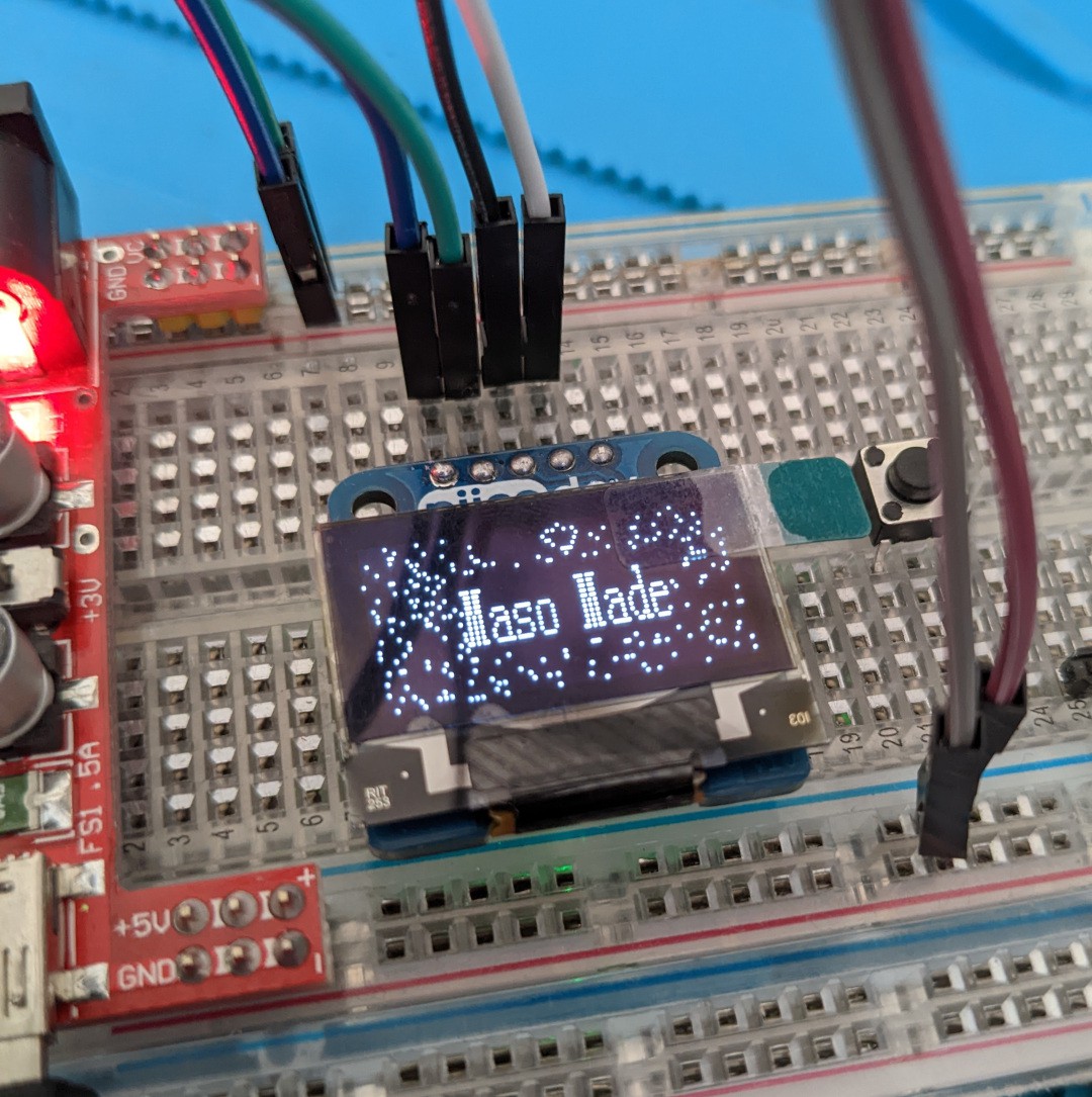
Thus began my journey into debugging the SSD1306 display where I found the worst aspect of the Digispark dev board system. Their specific libraries existed outside of my managed Arduino library folder and caused me much grief in the error messaging where I could see the display was not initialising in the proper way. While I eventually wrangled it to work to an extent I kept hitting walls with the devboard such as it's power delivery being pinned to 5V, which was less than ideal when I was aiming to get a 3v battery to run the whole thing.
Step 2: ATtiny85 Chip
When all hope was lost I decided to throw caution to the wind and just work off a bare ATtiny85 with an UNO as the ISP. It was like night and day after I got it blinking an LED, then powering up the OLED in a better many with Tiny4KOLED and TInyWire libraries working to their full potental.
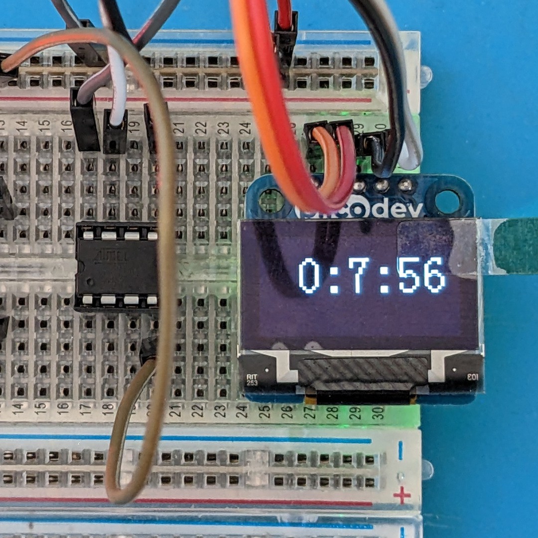
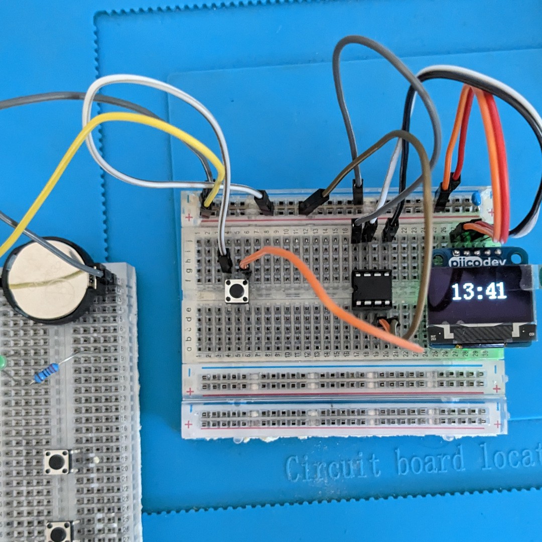
With the code being in a somewhat functional state for timekeeping. Then began the implementation of how to set the time with physical buttons. V1 had separate "Hours" and "Minutes" buttons the intention with this version was to always have a single "Time" button that incremented the minutes. I thought PB1 (PIN6) would be the most suitable point to wire up the button using an internal pull-up. However I then found that with the I2C implementation of TinyWire that wasn't possible and I promptly moved it to PB4 (PIN3) and just like that, it started working. Then it was a matter of throwing on a 3v battery and I was one step closer to moving it to a move fixed arrangement.
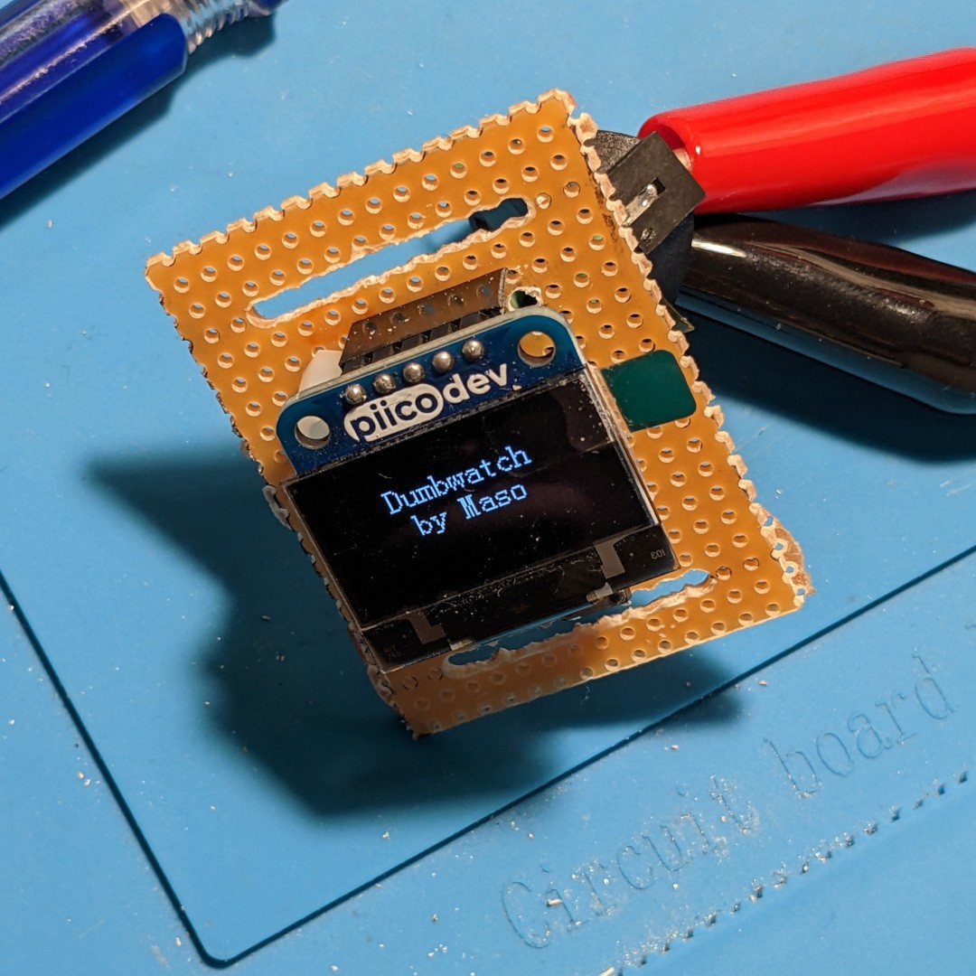
Step 3: Stripboarding
At this point I was feeling very confident in the build. Having proven my design was viable was every required part working effectively on the breadboard was a relief. The final step of this version would involve strip boards that would make laying out the pins a very easy exercise. After marking out the intended footprint of the watch (50 x 50mm) I plotted the intended runs for the parts. While the DIP-8 footprint worked effectively with the stripboard, I found the need to flip the SDA and SCL for OLED a tricky exercise using solid core wire to make the routes.
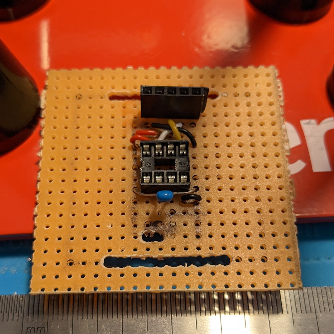
The cutout between the capacitor and the wider hole for the watch strap is the passthrough for the battery wiring.
Step 5: Power Up
With the watch assembled there was one last step before I could wear my creation. That was to ensure that the power was working out. V1's construction was disorganised at best, which led to power issues that ultimately resulted in several cooked ATmega's. Going through three of those chips made me especially cautious with powering this up for the first time. First power-up led to the discovery of a short that was quickly fixed. Finally I was greeted to a most welcome sight:
The final step was attaching the CR2032 battery holder and enjoying the results.
Discussions
Become a Hackaday.io Member
Create an account to leave a comment. Already have an account? Log In.