Close
0%
0%

Vacuum System for Deposition

I have been putting a system together for the past few years to do different kinds of deposition.

Similar projects worth following
I have been interested in vacuum technology for a very long time, since I was a kid actually. I always wanted to make my own neon signs. I few years ago I started putting together a system after I got an old Technics Ion Mill setup from a friend. I recently got a whole new chamber and am redoing it and getting it ready to do sputtering, evaporative, and e-beam deposition.

​I picked up the vacuum system from Portland State two weeks ago from a professor I know. It was too big for the little things they do and by the time it warms up and pumps down there is no time left. So they decided to get rid of this system and build a much smaller system to replace it. As they used it it was set up for doing evaporative deposition and DC sputtering. The sputtering head was removed but the evaporator was left. This originally came out of Tektronix,

So, some of the specs:

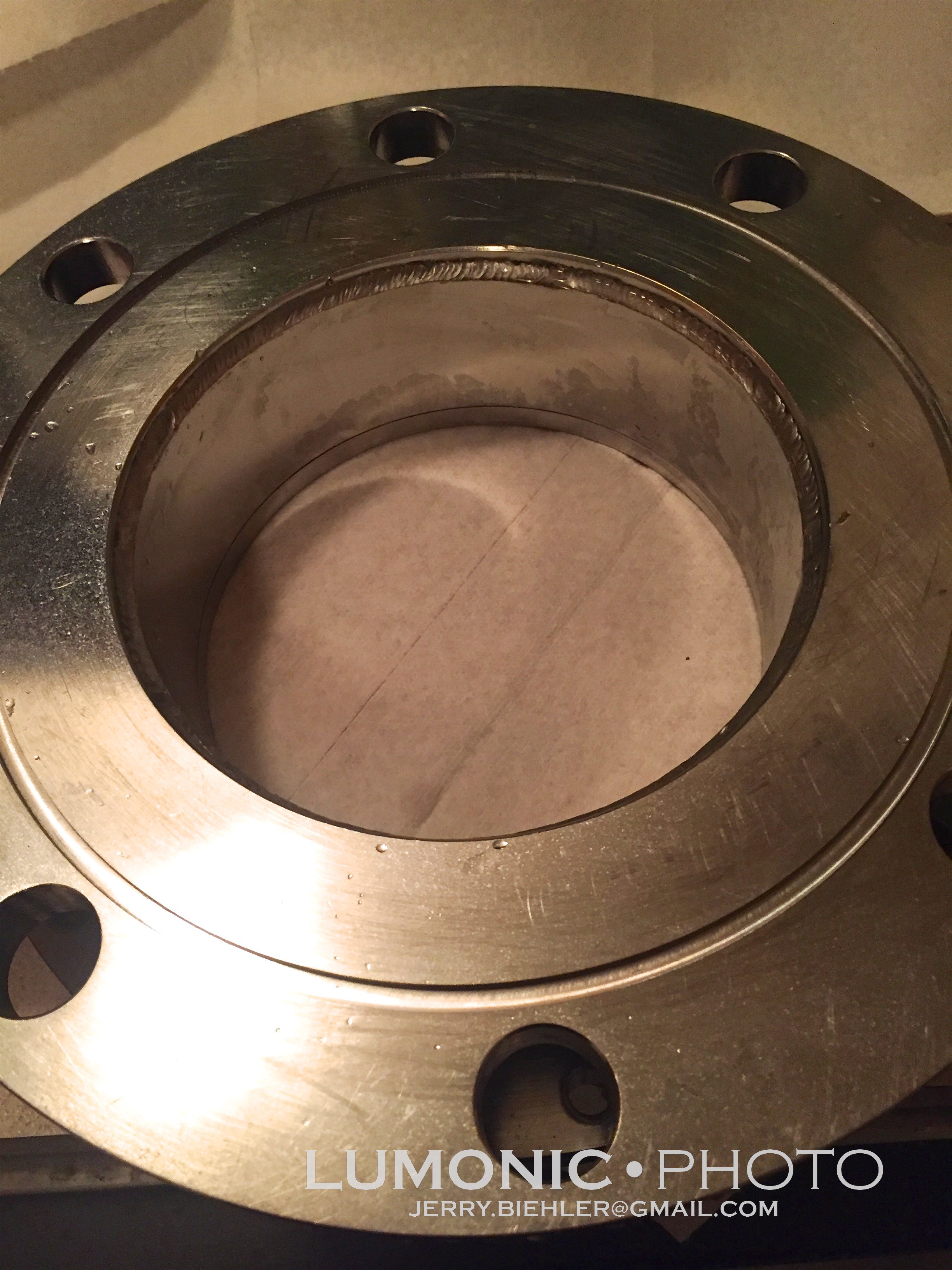
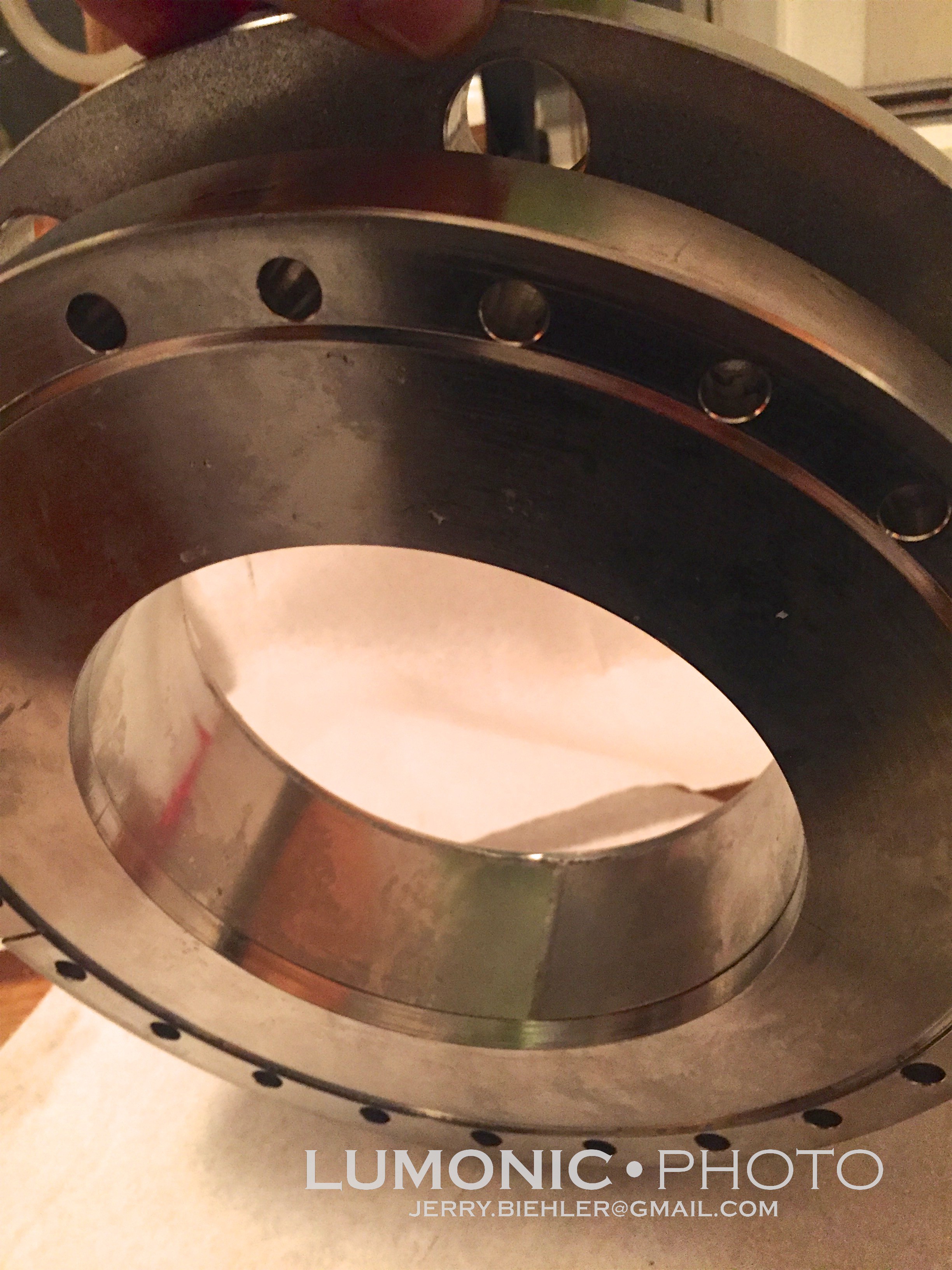
• 26" Stainless bell jar, appears to be a Cha. The lower ring looks to have been added later and is held in place by clamps. The base has a rotary feedthrough for the shutter and a bunch of standard 1" holes for other feedthroughs.
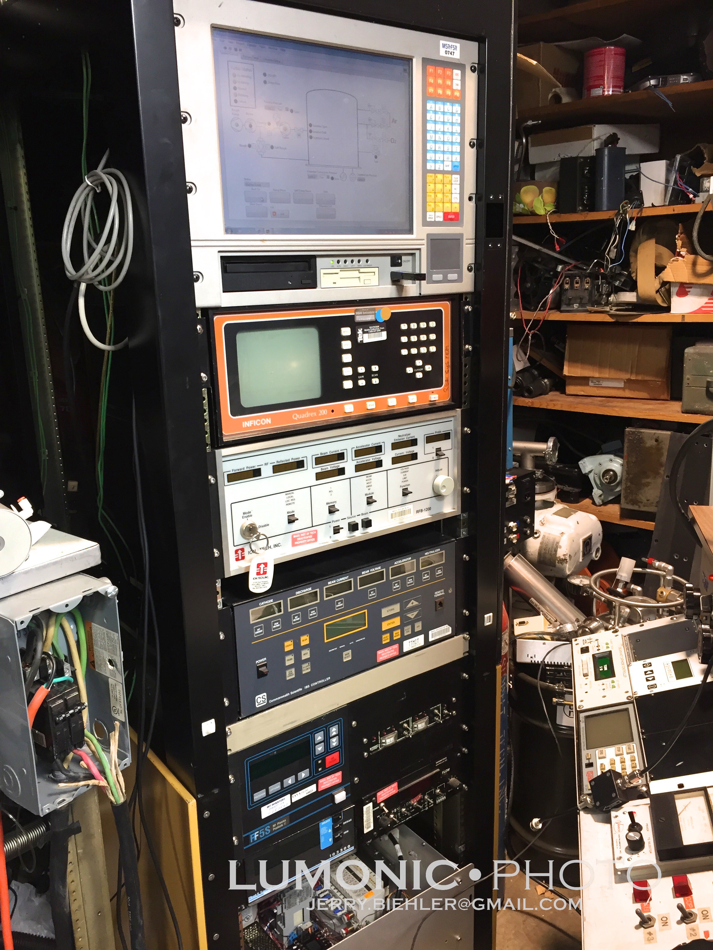
•​ Leybold XTC film thickness monitor and Airco crystal head
​• Lesker Ion Gauge Controller
​• Varian Extrion thermocouple gauge and system control panel
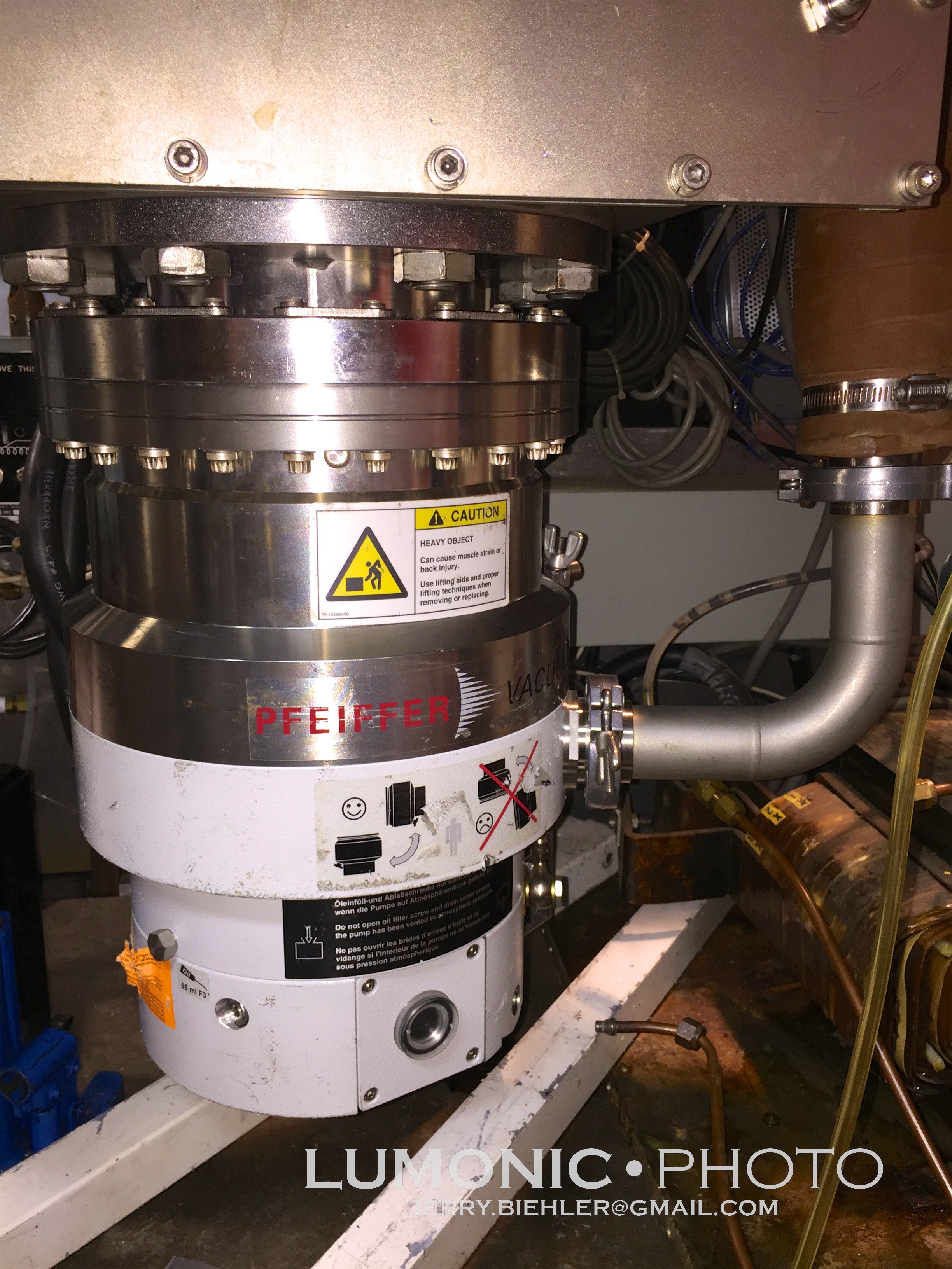
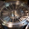
​• Varian 6" Diffusion Pump
​• Leybold Ruvac WA-150 Roots Blower
​• Leybold D30AC Roughing pump
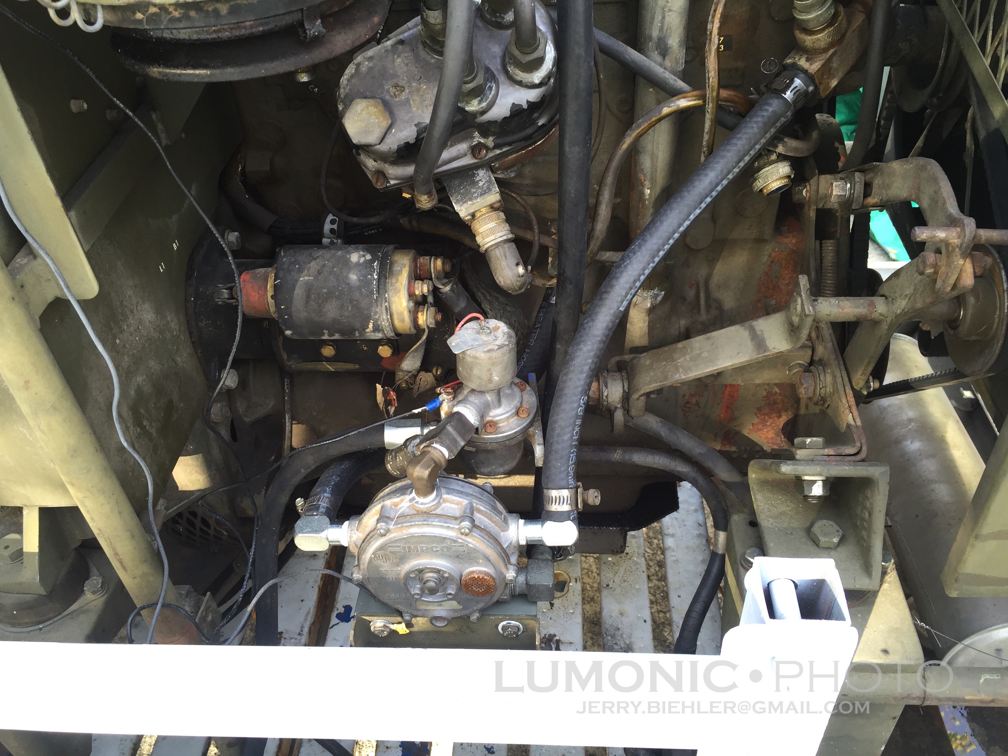
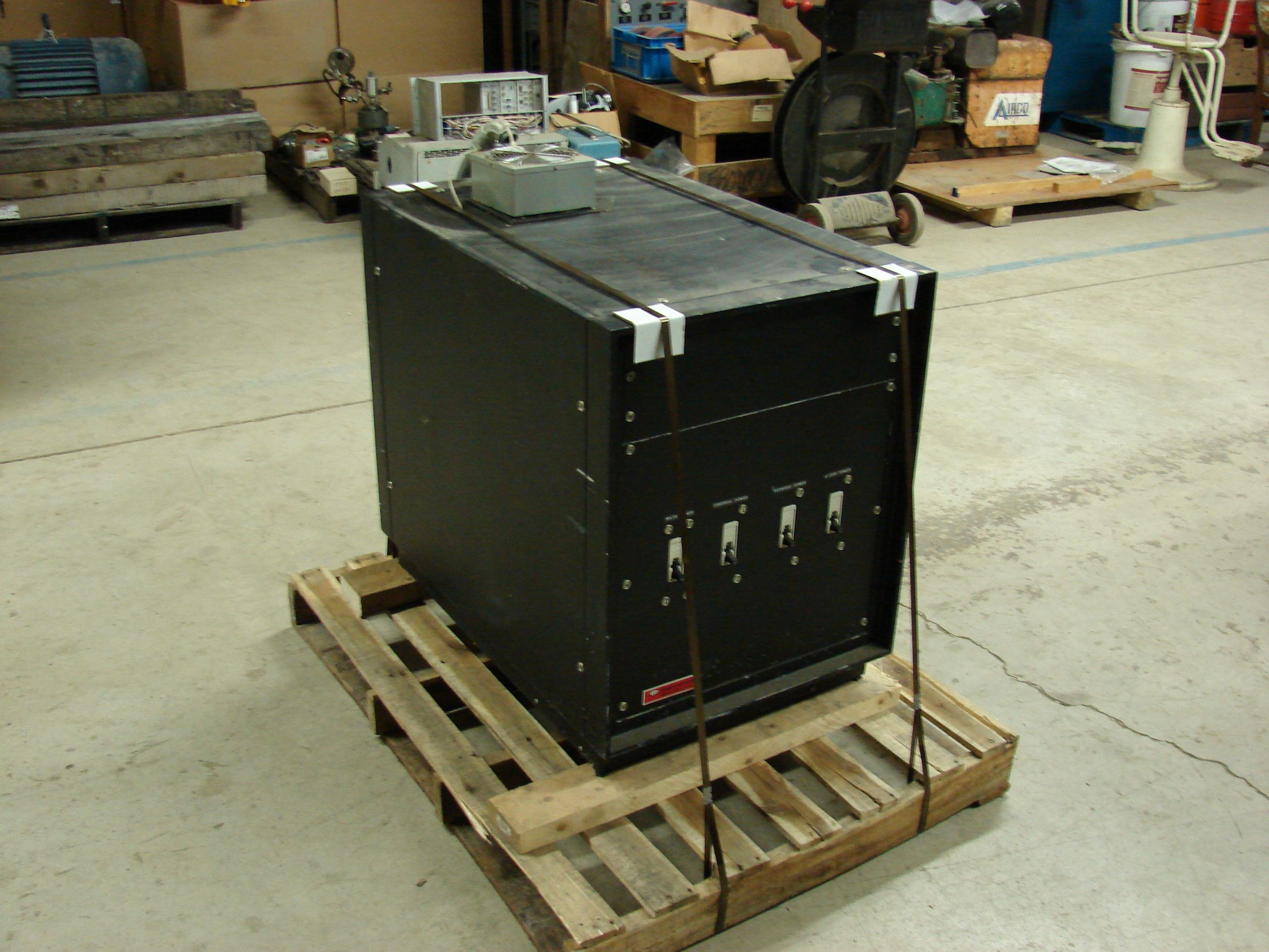
​• Water cooled evaporation transformer and control, control is homemade and transformer appears to be a varian.

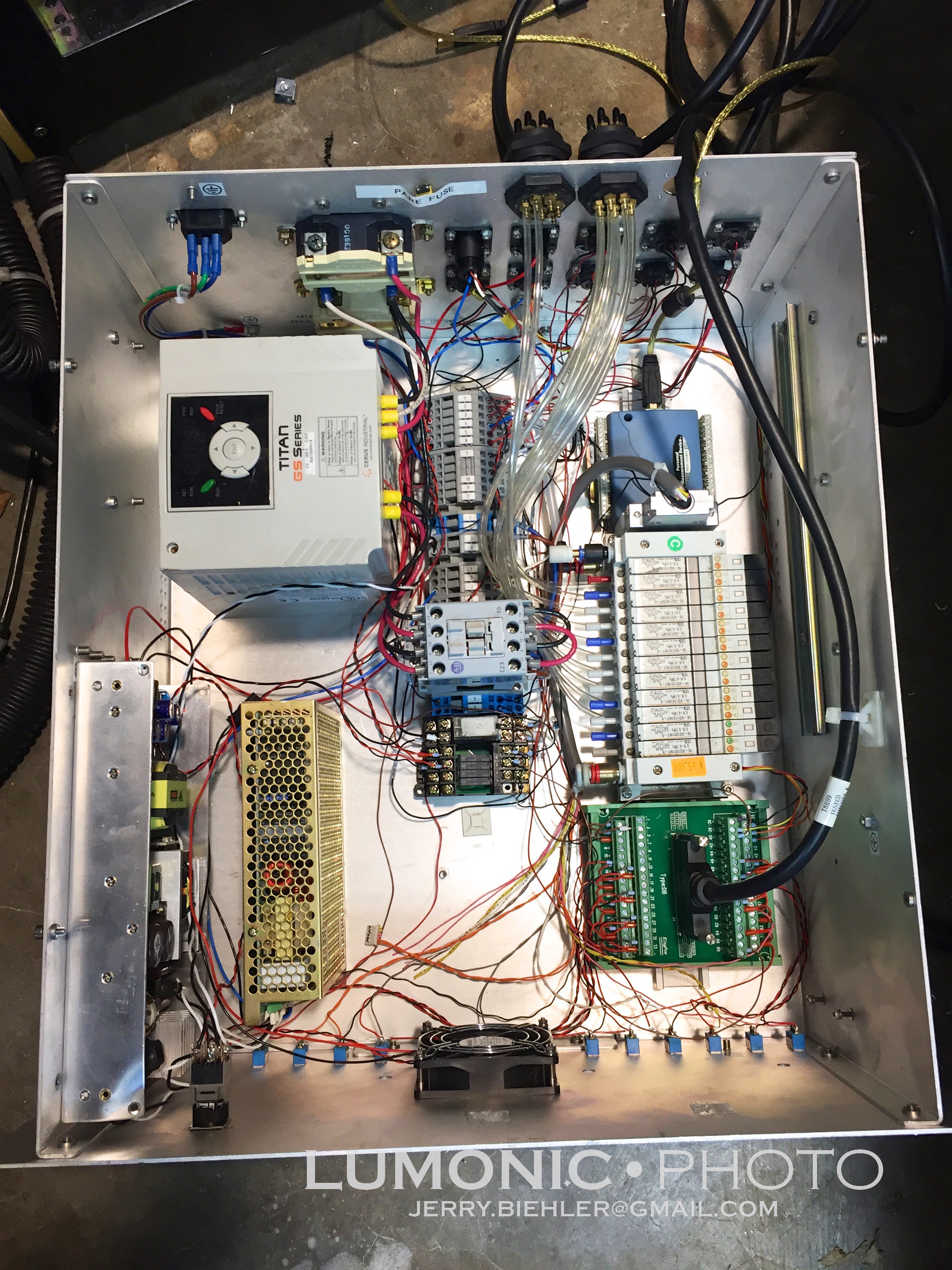
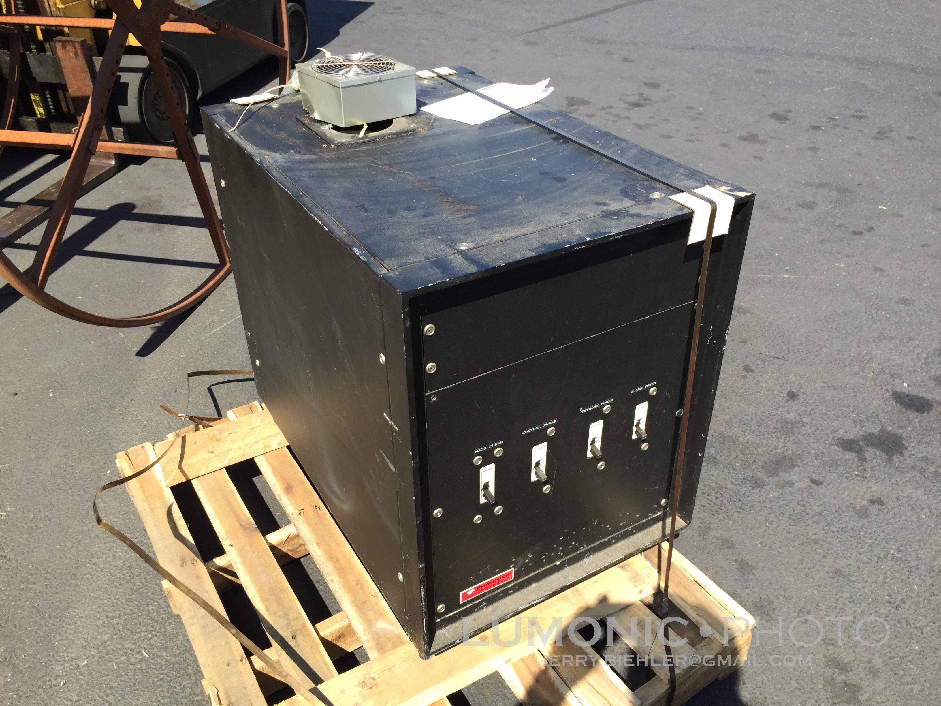
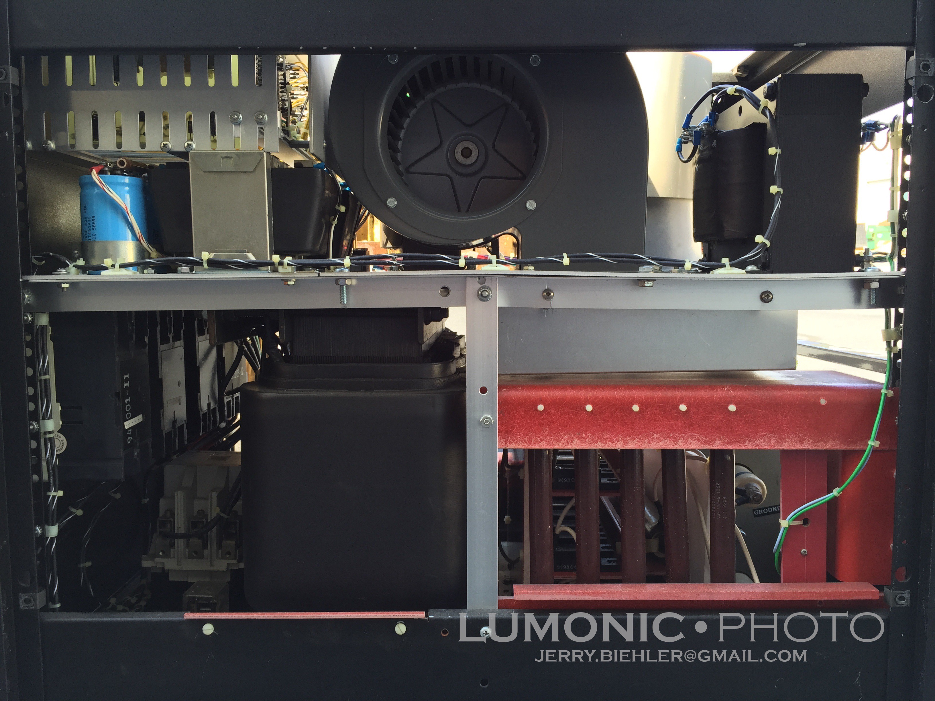
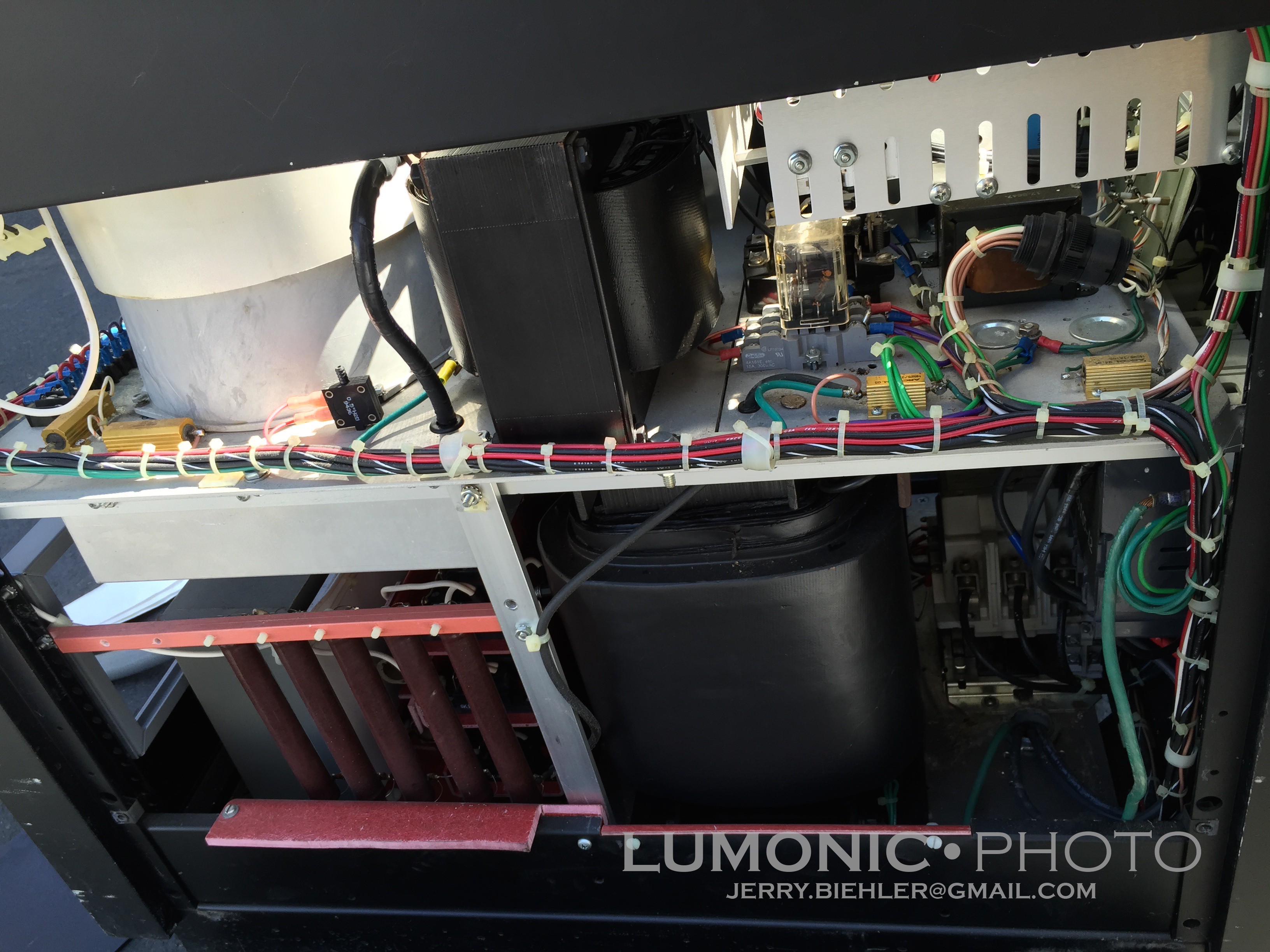
Several issues. Wiring is a mess. I am probably not going to worry about that too much. The one thing I am worrying about is they are using one hot leg and the ground as neutral. Not kosher! I am installing a 500VA 240 to 120 control transformer to provide the 120v power for the components of the system that can't run on 240. I am also installing a master power contactor and a bucking transformer to drop the 240 to 208 for the RF generator I have.

What I have done so far:

• General cleaning, it was pretty bad inside. I used a mix of Varian vacuum wipes and mineral spirits to clean out the bell jar. 
​• Installed a air/water heat exchanger with fans and pump to keep the diff pump, exam transformer, and crystal head cool.
​• Installed my Dymaxion 100 AMU RGA and it's associated Inficon IPC-2 pressure reducer. It is mounted to the base ring to the sole conflat fitting on the base. I still need to install the little Inficon Turbovac 50 turbo pump on the reducer. This will allow me to sample partial pressures up to 150mTorr though the IPC-2.
​• Installed a new Inficon bakeable crystal monitor head, this is mounted through a conflat tee on the same spot where the RGA is attached.
​• New bell jar o-ring, 27.25" ID. I messed up the one on there putting the top on when I got it. Only $4 from APM!
​• Readjusted the ion gauge controller, someone had the settings way off. I couldn't understand why I couldn't get it below 2x10^-5 torr. I hooked up a couple other gauge controllers and found it was reading a whole decade high.
​• Working on an leak on the air cylinder of the gate valve, it leaks when open. The o-ring on the piston is shot.
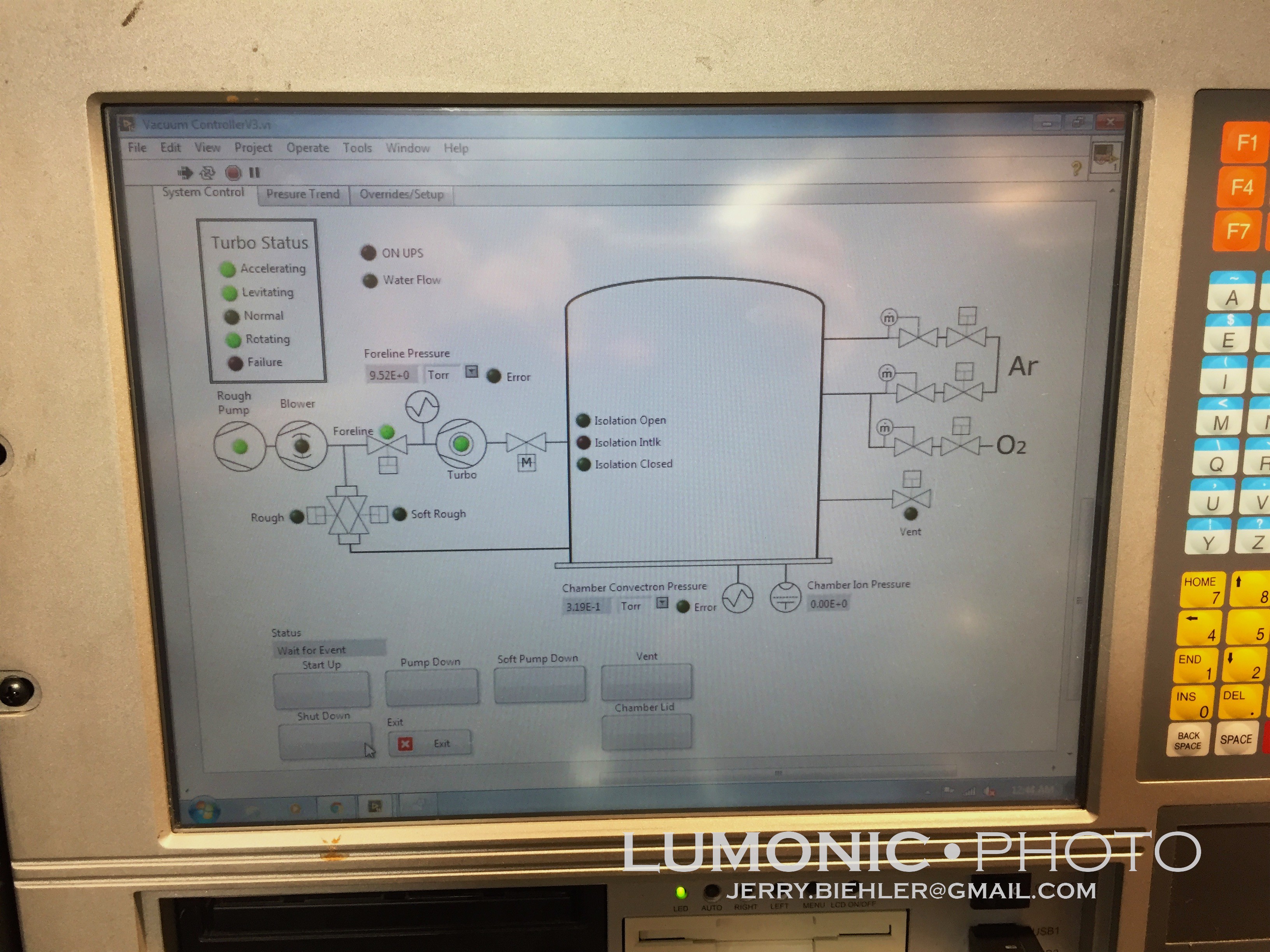
​• Fixed some of the wiring in the control panel, got all of the pilot lights working, added switch and light for main contactor as well as rewired for a 24v solenoid to control the gate valve.
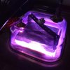
​• Installed a power feed though on the top of the jar. I have a 1kw quartz halogen lamp installed for bakeout and substrate heating.


​What's next:

• Replace the XTC crystal monitor with one of the Sycons I have, a lot more features, dual head capability.
​• Build controls for the valving on the RGA.
​• Install interlocks for the vent and gate valve, they should not be able to open at the same time.

Bucket List:

​• Build a 2" sputter gun
​• Build a 4 pocket e-beam evaporator
​• Replace the diffusion pump with a turbo pump. This will eliminate 
back streaming. I have two pumps right now, both made by Seiko Seiki, one is 1000l/s and the other is 2000l/s. I only have the control for the smaller one.

Adobe Portable Document Format - 4.75 MB - 05/06/2023 at 07:07

Preview
Download

Adobe Portable Document Format - 7.05 MB - 05/06/2023 at 07:07

Preview
Download

Adobe Portable Document Format - 115.62 kB - 05/06/2023 at 07:07

Preview
Download

Adobe Portable Document Format - 12.04 kB - 05/06/2023 at 07:07

Preview
Download

Adobe Portable Document Format - 4.04 MB - 05/06/2023 at 07:07

Preview
Download

View all 29 files

  • Working on the small system again

    Jerry Biehler03/29/2022 at 06:15 0 comments

    Finally working on the small system again. I did get the copper conflat seal and installed that and have not touched the system since.

    Couple weeks ago I decided to take another whack at the system. First issue I have found is the turbo is not happy after a couple hours of running. Not sure what going on, it starts vibrating, I think the bearing I replaced is not up to snuff. I did try putting the turbo on a dedicated chiller to see if that stops it thinking that maybe the bearing was getting hot and the race gets a little looser but it didnt fix the problem. So I am trying to get a quote from alpine bearing for a new one.

    Then the thermocouple gauge head died. Got an old Varian 843 from a friend to replace it. Much nicer than the old one. Next I had more water leaks. One of the brass parts of one feedthrough was cracked though and another fitting was split. I machined a new part and replaced the other. 

    Thats when I found out I had a leak someplace. Couldnt get below about 8x10^-5 torr. I tried spraying everything with alcohol to find the leak that way, nothing. Tried argon, nothing. Got out the RGA. Its was dead, would not talk to the laptop. Replaced that comms board. Now it talks but shows a huge spike from about 5 amu to 20amu. As in it maxes out the scale. I took the RF section off a spare unit and stuck it on there and that seemed to fix it, I was able to retune it and was good to go.

    The next day I went to Target and picked up a bottle of balloon helium. Rigged up a flowmeter and a hose to make a helium sprayer and started going around each joint. Eventually I found the ASA flange between the isolation valve and the chamber was leaking like a sieve. I took the eight 3/4' bolts out that held it together and used a toe jack to lift the baseplate off. It was pretty dirty. I pulled the o-ring out and ordered some replacement but I measured wrong. Whoops. So I cleaned the old one, put some Krytox on it and put it all back together. Pumped it down and after about an hour or so it hit 9.5x10^-6. Much better!

    Next thing was to replace the big ferrofluidic feedthrough for the shutter. It was so big that it was partially blocking access to the adjacent baseplate ports which I needed for other things. I remove the feedthrough and installed a bellows type rotary feedthrough. I adapted the existing shaft arm to the new feedthrough and installed a pneumatic rotary actuator to open and close the shutter with s small solenoid valve. This way I will be able to control it with the deposition controller. 

    While I had the table off I found some pretty major air leaks so I went about fixing those. While I was doing that I discovered the people that had pieced this system together had connected the differential pumping connection of the planetary rotary feedthrough to high vacuum instead of the roughing line. A differentially pumped feedthrough has a shaft sealed with two o-rings. the section between the two o-rings is pumped down with the roughing pump, this creates a simple feedthrough that handles high vacuum. 

    I hooked it up to the roughing line like it should be and found that the feedthrough was leaking, Bad. I couldn't even pull 2 torr in the roughing line with the roots blower pumping. I could actually hear the thing leaking. Luckily I had a spare offset drive that was brand new and just replaced the existing one. When I got the old one off it was a mess. I could see where stuff was falling from the bearings, tore it apart and the bearing just fell apart. I tore it all the way apart and pulled out the two o-rings which were toast. Cleaned the housing out and installed new o-rings with krytox. Polished the shaft where it ran against the o-rings and knocked off burrs from people messing with it in the past. I found a new bearing in my stash and took off one shield and cleaned out any remaining lubricants and put in some krytox and put it all back together. Much, much smoother. I also took the final drive bearings out...

    Read more »

  • Turbo on the small system

    Jerry Biehler01/19/2018 at 08:18 0 comments

    On the smaller system I picked up a 1000l/s Pfeiffer turbo to put on it as well. It had a bad bearing and I picked up another one and installed it. Oil was a pain to come across, very specific for the pump, a fomblin. 

    The biggest issue was mounting it to the machine. The old pump was mounted to the cold trap with a 6" ASA flange. I was hoping to remove the cold trap and connect directly to the isolation valve but it turns out that the cold trap is what supports the whole system. I got a 6" ASA flange and a 10" Conflat flange from a friend and welded them together to make an adapter. I used a reusable rubber conflat seal instead of the single use copper ones and it looks like that was a mistake, sprayed down the joints with IPA and found that the rubber  seal is leaking. A copper gasket is on the way. 

    I have been waiting to finish the control for the other system to run the roughing pump and blower, they are shared between the two systems. 

  • LabView.... Wheee...

    Jerry Biehler01/19/2018 at 08:07 0 comments

    I have had way more time on my hands than I would like lately so I have been digging into the vacuum systems. I had ripped out most of the old controls from the large system so I could build in interlocks. Also the new VAT pendulum valve requires RS-232 commands to open and close the valve as well as run it in pressure control mode. 

    I decided to use LabView to control it, National Instruments offers the 2014 version for home use for $50, pretty good deal. I picked up a ADLINK PCI7256 latching 16 output/ 16 input card to handle the digital IO and a PMD 1208FS USB Data Acquisition unit to handle analog input from the two Mini Convectron 275 vacuum gauge heads I am using to replace the old thermocouple gauges with.

    LabView is quite a learning curve. Both the IO devices I used have LabView drives which made it somewhat easy, though the ADLINK software that was supposed to make setup easier didn't work so I ended up just kludging something together with their examples.

    So, after a couple weeks of programming it, bench testing it, and building the hardware and cables I finally have something that works. Still need to tweak some of the program here and there but it seems pretty much good to go. 

    Started wiring it up today to the machine and can at least rough down the turbo and control the pumps. Next I need to patch in the rest of the cables. 

  • Gun Pocket Control

    Jerry Biehler12/26/2015 at 06:11 0 comments

    So now that the e-beam supply works... well, at least I think it does. I have no way to build a 12+kw load for 10kv. Thats a lot of big resistors. I need to get the gun control working. The e-beam gun has 4 pockets that are rotated from the side, that's what that little stepper motor I stuck in a sealed container is for. To drive that I chose a Compumotor OEM750 indexer. It is a little self contained unit that has a battery backed up memory that can be programmed to do different things based on a few different inputs it had. It is actually pretty awful to program, there are three "trigger" inputs and three "sequence" inputs. The indexed can store 7 programs in it and the sequence inputs select the program in binary. The trigger inputs turned out to be totally useless for this project. When a trigger call pops up the program just stops there till one of the trigger inputs changes state according to the program. There are no "if" statements or anything. Really annoying.

    It also has a couple programmable outputs which ended saving my but. I needed the indexer to home the crucible turret at startup and since the trigger inputs are useless I had to write one program for homing and one program each individual pocket. Since the outputs will sink as well as source I tied this into the "4" bit of the sequence inputs, these inputs normally pulled high. So when the indexer powers up the bit is pulled low and it is set to run sequence 011 (3). The homing program runs and then it sets the "4" bit high which shifts all the sequence inputs to the 1XX range. At this point the two lower bits will select the pocket position, 00, pocket 1, 01, pocket 1, 10 pocket 2, and 11, pocket 4. It actually worked. I had to set the other output as a "pocket good" output signal to tell the deposition controller that it is in position. Again I butted heads with the programming in this thing. When it runs a sequence it just runs it over and over so if you turn the output off at the beginning of the program and on at the end it just cycles the output as fast as it runs through the program. I added some delays into the program, it seems to work now.

    To control everything I picked up a Sycon STC-200SQ deposition controller. I have actually picked up a few of these over the years for cheap on ebay. The SQ allows you to do sequencing which allows you to write recipes to automate the coating process. It has what is basically a simple PLC programming area in the software that allows you to program the 8 inputs and 8 relay outputs on the back. The manual happened to have a program in it to control one of their pocket drive units so I modified it to do the binary control that I use to control the indexer. The controller moves to the pocket with the material selected and does a ramp and soak and then opens the shutter over the source and monitors the deposition rate through an analog output to the e-beam power supply and final thickness by the shutter.

    For a lot of materials you cant just let the e-beam sit in the middle of the crucible, you need to move it around the surface of the source material. To do this there are electromagnets on the gun that will sweep the beam across the surface much like the yoke on a CRT does. I had though about building my own driver for this, it can be pretty simple, just a couple H-bridges and something like an arduino. Then I got to to looking at the designs and they are a little more than that, they need to bias to get the beam in the center and stuff.

    A MDC E-vap Programmable Sweep Controller popped up on ebay and I managed to snag it for $200. It worked, mostly. The backlight for the little LCD touchscreen was toast. It had a pretty large CCFL behind it and I could not find a replacement so I wired up a bunch of white leds in series and put them inside the old CCFL lamp tube. I bypassed the CCFL inverter to drive the led string with 12 volts directly. It actually worked out pretty well. it does have some hot spots where the leds are concentrated...

    Read more »

  • E-Beam Power Supply Repair

    Jerry Biehler12/25/2015 at 23:36 0 comments

    With the generator running well and the interconnects made for the power supply and control box I decided to power the thing up and see if it worked. I fired up the generator and flipped the breakers on the front panel. Filament voltage was good. After letting the tube warm up I satisfied the interlocks and hit the HV button. The volt meter immediately pegged out. Thats not good. I put a HV probe on the output and yep, full voltage with no regulation.

    Looking through the schematics I see that the screen supply voltage is way low. It turned out two of the four of the screen bypass caps were shorted out. While checking voltages I also found that there was no grid voltage at the socket. This was from a open 10k, 30W resistor on the grid supply to the tube. So with no screen and no grid the tube was just a big diode. I ordered replacement caps and resistors from Mouser and installed them. Powered it all up and it works, fully variable from 0-10kv. While I was waiting for parts I picked up a used tube (4CX15000A) off ebay from a very helpful seller who used to work with these kinds of tubes in the past. It looks like I dont need the tube, yet, but it is nice to have a backup.

    I have no idea why these caps shorted out or why the grid resistor blew. I guess I will have to wait and see.

    The offending caps:

  • Generator Progress

    Jerry Biehler12/25/2015 at 23:18 0 comments

    I have not updated in a while. So here is what has been going on:

    Generator has been repaired, the number 1 cylinder had a bent valve end where it meets the lifter. It looks like at some point in the past the valve got stuck and the valve end was bent. Someone broke it loose with vise grips and continued to run it this way. The bent end caused the valve to push to the side and wobble out the valve guide. I replaced the guide and the valve and installed a new gasket set while I was in there.

    I managed to find an original manual for the gen set that was full of useful info like the part number for the stock muffler which I found online for $12. Other info like the make and model of the power outlet and stuff like setting the velocity governor were handy to have too.

    I could not find one of the original cast exhaust couplings so I just made my own. I got a flange from he local muffle shop and made the rest out of a 1-1/2" rigid conduit sweep and various pipe fittings which replicated the original pretty closely. It runs much quieter now, in fact the noisiest thing about it is the cooling fan.

    One thing I discovered during all of this is the propane conversion that was done would not work at any useful power output. The setup on the generator as I got it was to use vapor from the propane tank. From figures online I would need a 250 gallon or bigger tank to be able to keep up with the vapor demand without freezing up. I picked up a IMPCO vaporizer off ebay and installed it in the place of the gasoline engine heater. I bought a ASME 30gal propane tank off craigslist to feed it, that should give me about 24hrs run time at minimal load and about 12hrs at full load. The generator and tank were mounted to the trailer I picked it up with.

    The power plug that mates with the connector on the generator is still made, but costs over $600. Even one on ebay is over $200. I ended up making a pigtail with a twist lock connector on it that connects to the output studs on the panel. This connects to the 50' of 6/4 SO cord I am using for an extension.

    I still need to make the replacement back and top covers, that can wait for now.

    Tank mounted to trailer:

    New vaporizer:

  • Picking up the beast

    Jerry Biehler09/12/2015 at 06:32 0 comments

    Wednesday I drove up to Marysville, WA from Beaverton, OR to pick up an old PU-26A/U genset that was on craigslist. Apparently it has been serving as a standby generator at the Lake Goodwin Fire Dept up until about 8 years ago when they finally got something newer. It has been converted to propane with a Century valve, regulator, and carb. They guy I got it from got it from the guy who got it from the FD and he managed to get it running. I paid $550 for it.


    It needed new hoses bad, it has the M38 Willys engine in it and the little bypass line was rotted though. I replaced all those lines and installed a new fan belt. I pulled the thermostat off and checked it, old bellows style, still works. But I just couldn't keep the thing running. Eventually found the propane hose was full of dirt, some bugs must have decided to try to make a nest in there.


    Video of first run, generates just fine.


    I noticed some noise in the exhaust, today I traced down a couple errant wires, picked up some Automate 2245 plugs from Napa (Less than $8 ea!), and popped the side cover off and adjusted the valves. There was little or no lash in every exhaust valve. Put it all back together and it seems to run smoother.


    Next thing to do is to build an exhaust system, Does anybody know id the M38 engines used 1-1/2" or 1-3/4" exhaust? I looked it up and couldn't find anything.

  • Powering this mess

    Jerry Biehler09/05/2015 at 04:10 0 comments

    So, how do you power a 12kw three phase power supply on single phase in a home garage? Answer: You dont.

    Three options available.

    1. VFD: Well, we saw how well that worked out
    2. Phase Perfect, it is a device that electronically creates the third phase. They work very well and can give you power better than utility quality. But one that can run this power supply is about $5k. And draws at least 100A at 240 single phase.
    3. Rotary Phase Converter. For this supply I would need about a 40HP phase converter to run at 12kw, that draws up to 150 amps.

    I have a 100A service.

    Answer: You dont.

    So, how do you run the power supply? A generator. A lot of military generators out there have three phase output as standard. I found a old (1956) military generator that will supply 12.5kw at 208 or 240 three phase. Just what I need and the price is not bad. It is not terribly efficient but it is my cheapest option. This one used a Willys jeep engine as the engine and has been modified to run off of propane which is nice since I dont have to worry about gas going bad in it while it sits. I also dont need to worry about the fumes killing me.

    Yeah, my neighbors are going to LOVE me!

  • Power Supply has Arrived

    Jerry Biehler08/27/2015 at 04:57 0 comments

    The power supply showed up today. Barely made it here on it's pallet and just a bit of minor damage.

    It was not banded very well and the fan box on top was ripped off. No big deal, took like 10 minutes to fix the box.

    Popped it open to find mice had made a nest in a couple areas, one being on top of the giant power tetrode. Washed the tetrode down and it cleaned up pretty well, bet it is going to stink like all get out the first time it warms up! The second nest was vacuumed away. It appears they had no appetite for wiring like I have seen in the past.

    Everything looks in pretty good shape, at some point a screw on one of the trays came out and the air ducting for the tetrode bent a bit. O this pic you can see black transformer and it's control contactor on the bottom left, the diode section is on the bottom right with discharge resistor for the filter capacitor. Top left is what I believe is a 240 to 120v control transformer. To its left is the cooling fan for the tetrode and I think the black potted transformers on the far left are for grid and screen control with the control card rack above.

    Nothing terrible exciting on this side, you can see the tube socket/chimney on the far left and more discharge resistors below that.

    Here you can see the huge Eimac 4CX15000A, 15kw, power tetrode that handles voltage regulation for the power supply. The filament transformer for it is on it's left. The tube's filament runs at 6.3v at 160 amps. The filament shows continuity so I am hoping it is good.

    I am waiting for the parts to make the interconnecting cable between the power supply and it's controller to show up. I am also gathering the last couple parts to make the filament transformer box.

  • Back to the drawing board...

    Jerry Biehler08/21/2015 at 06:40 0 comments

    So, I have scrapped the idea of getting this supply running for the e-beam gun. Finding a tube has been very difficult so I picked up a Thermionics EBPS15, 15kw, tetrode electron beam power supply to do the job, it is good for up to 10kv at 1.5 amps. It uses a 4CX15000A tetrode for regulation. I got the power supply itself from a guy in Tennessee and the control box for it from BMI Surplus. Thermionics was able to supply me with a very complete manual so I should be able to get it going.

    I do need to make the interconnecting cables and the filament transformer box. It contains the SCR controller for the filament transformer, the current sensor, and the filament transformer. Lucky for me the details of the operation of the unit are very complete and was able to figure out how to build it. I had a hall type current sensor from one of the old chassis that I picked up in california that will work for feed back and I can use the Airco filament transformer I picked up earlier. The controller uses the current sensor to detect emission current and then sends a 0-10v signal to the SSR module to control the power to the filament which limits emission. I picked up a Eurotheum 425A SCR controller off ebay which is rated for transformer coupled loads so I should have everything I need.

    Using this supply instead of trying to roll my own gives me good regulation and also Arc Detect. During deposition you get arcing in the chamber, this power supply will detect that and roll back the current and recover automatically. The reason for the arcing is not very well understood, apparently.

    The control box showed up today and the power supply was picked up by Yellow Freight today and is on it's way, it should be here next week.

    New price on the power supply is about $40k, with the control box and shipping it is all coming to about $1200.

    Strapped down and ready to go:


View all 23 project logs

Enjoy this project?

Share

Discussions

Koji Tokura wrote 08/17/2022 at 07:29 point

Wow! What a wonderful array of devices!
I am building a miniature sputtering equipment at home for photography.
I mainly use materials available at DIY store, and now I'm struggling to improve the foreline trap of the rotary vane pump.

I look forward to your progress.

  Are you sure? yes | no

leminememinem wrote 08/16/2021 at 08:17 point

I'm looking for the same solution to make the automate vacuum program for my project. You can see here more detail about it https://vacuumvirtuoso.com/best-canister-vacuum/

  Are you sure? yes | no

bjorn_borgelink wrote 04/20/2015 at 10:05 point

I work with the Balzers Bak 600 e-beam evaporator, and want to build an evaporator on my own, when I have more "spare time".  Reading your story on Hackaday increases the need to have one on my own. Keep us informed of your progress!

  Are you sure? yes | no

bjorn_borgelink wrote 10/22/2014 at 15:07 point
Hello Macona. I was wondering, which type of layer do you plan to deposit and to sputter on your substrate? And what is your substrate?

  Are you sure? yes | no

Jerry Biehler wrote 10/30/2014 at 19:39 point
Various things, dielectrics for mirrors and filters, metals for mirrors and coating samples for my SEM. Whatever I feel like!

  Are you sure? yes | no

Jasmine Brackett wrote 08/06/2014 at 20:39 point
Hello macona, I've left a comment on http://hackaday.io/project/189#j-discussion-7098 letting you know what's required for your projects to be considered for the next round of The Hackaday Prize. They apply to this project too. Thanks, Jasmine

  Are you sure? yes | no

Similar Projects

Does this project spark your interest?

Become a member to follow this project and never miss any updates