 Just4Fun
During some surfing on Ebay I realized that with 4$ it is possible to buy enough ICs to build a complete Z80 system that can be done using a breadboard, and taste some flavor of retro computing.... So I did it and here it is the story!
Here is a video with the Z80-MBC in action:
and here with a smartphone (so it is explained the word "Mobile" in his name...) with a common OTG cable (the various test clips in this video were used for some measurements with a Logic Analyzer):
* * HARDWARE OVERVIEW * *
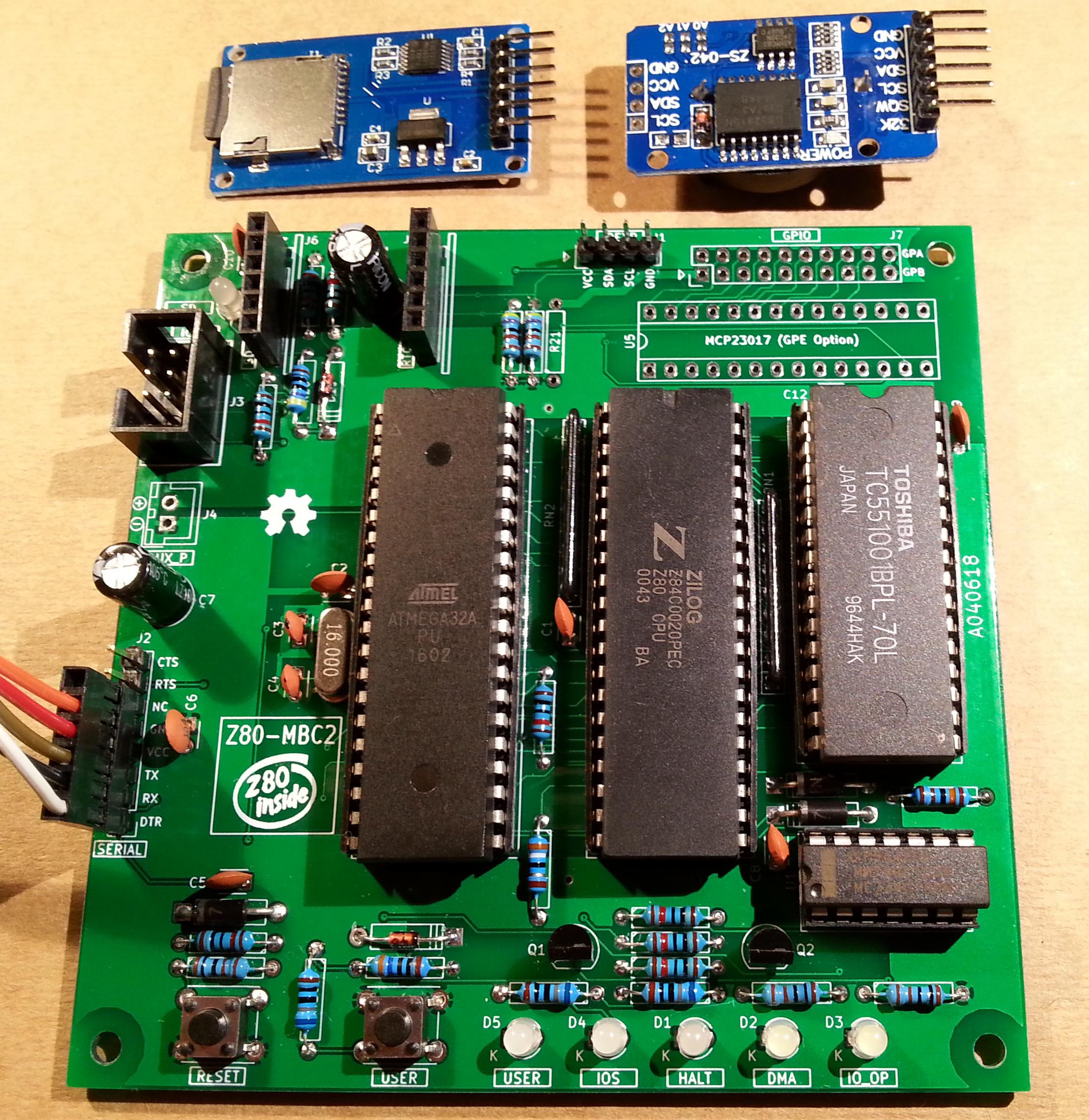
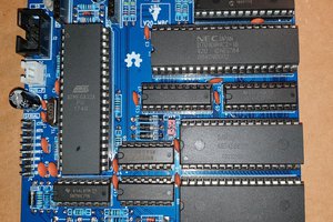
The needed ICs are:
- Z80 CPU CMOS (Z84C00) 4Mhz or greater ($1.16)
- Atmega32A ($1.70)
- TC551001-70 (128kB RAM) ($1.10)
- 74HC00 ($0.25)
Total cost: $4.21
The wires were taken from salvaged broken LAN cables, and the other components were salvaged from others unused breadboards.
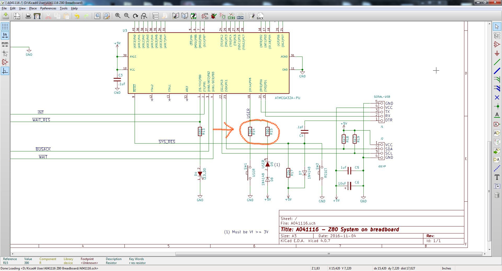
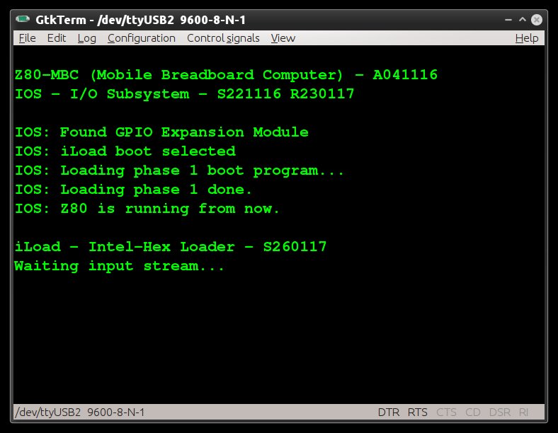
The schematic is attached in the Files section. The MCU Atmega32A is used as universal I/O subsystem, as Eeprom, and as reset and 4MHz clock generator for the Z80 CPU.
Into the Atmega32A it is flashed an Arduino bootloader taken from here , and it is possible to use the Board Manager of the Arduino IDE for that.
Flash the Arduino bootloader at first (with the method you prefer), next you can start to build the whole thing!
Of course I used the Arduino IDE to develop the IOS (I/O Subsytem) that interacts with the Z80 bus and "virtualizes" the peripherals seen by the Z80 CPU.
As oscillator it is used the internal 8MHz Atmega32A oscillator, so no quartz is needed, and from this one is derived the 4MHz clock for the Z80 CPU (so the "Internal 8MHZ osc." bootloader variant must be chosen when flashing the bootloader from the Arduino IDE!).
The 74HC00 is mainly used as RS flipflop to stop the Z80 CPU during I/O operation, giving the needed time to the Atmega32A to interact with the Z80 bus.
The 128kB RAM TC551001 is used only for half (64kB) because the Z80 address space is only 64kB (I've chosen this IC for the low cost).
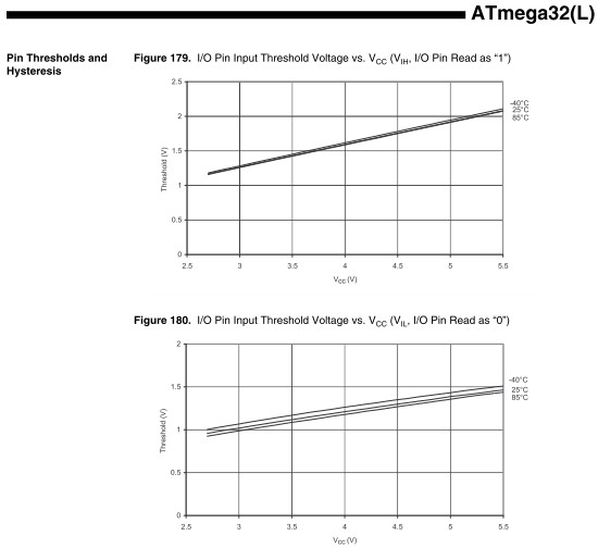
Note that only the CMOS version of the Z80 CPU can be used here. This because only CMOS version, under given condition that are respected in this schematic, has logical levels compatibles with Atmega32A and 74HC00.
NOTES ABOUT THE COMPONENTS:
You can use any Z80 CMOS speed grade, because the lowest is 4MHz.
The 74HC00 can be substituted with a 74HCT00 if you already have one.
The RAM chip TC551001-70 can be substituted with any suitable 64kB RAM (do not use < 64kB RAM).
The USER led (D5 in the schematic) MUST be blue or white just to be sure that V(forward) is >= 3V.
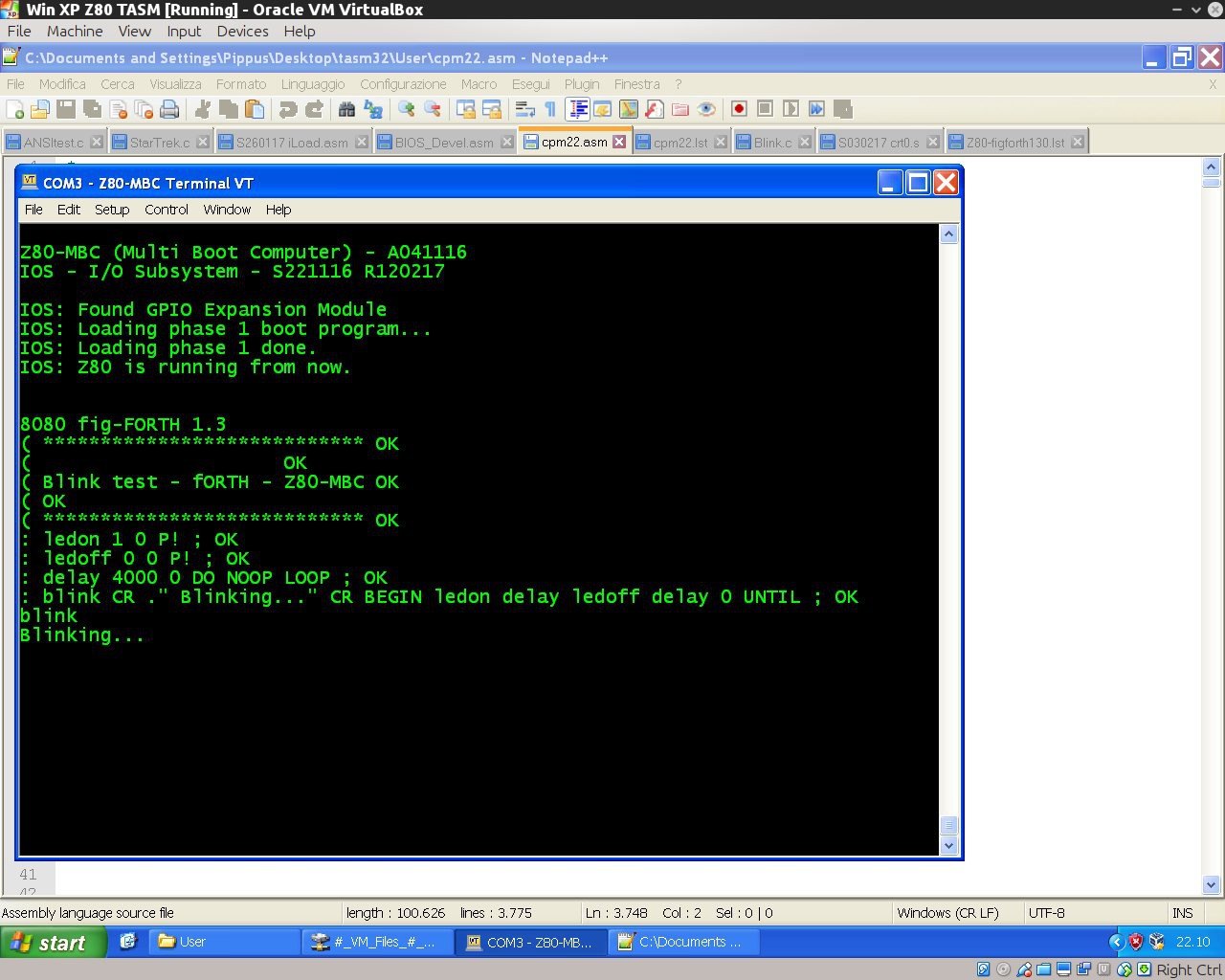
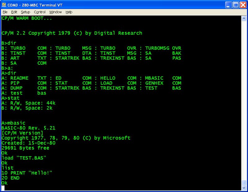
Here is a video that shows a simple basic program that interacts with the "USER led" and "USER key":
On the breadboard there are others status led: the HALT led turns on if an HALT instruction is been executed and the Z80 CPU is in a Halt state, the DMA led turns on during DMA operations when the Z80 bus is in Hi-Z, the IO_OP led turns on when the Z80 CPU is accessing a I/O virtual device "emulated" by the Atmega32A (as the serial port), the LED_D0 led is the classical "Arduino" led (that one connected to D13 pin on the Arduino Uno) that here is connected with the Arduino D0 pin and is turned on normally as a power on indicator.
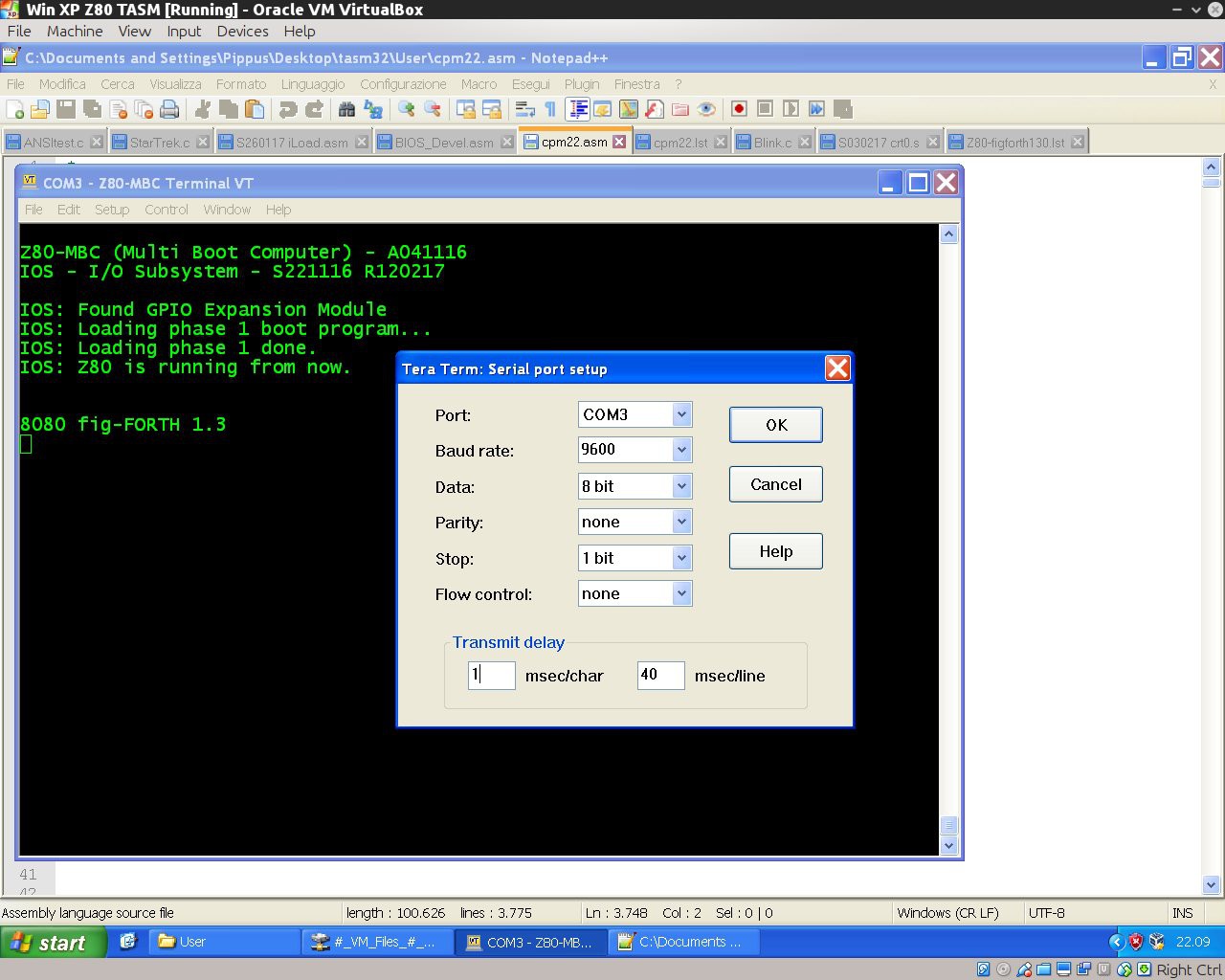
The serial port SERIAL-USB (see schematic)...

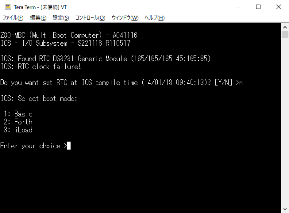
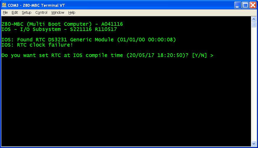 Press Y. If you are enough fast you have the RTC set up with the right date/time taken from the sketch compile time (if you are lazy like me you'll find this very handy...). In any case it is possible adjust the date/time manually too from the boot selection menu;
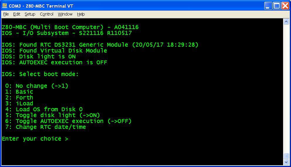
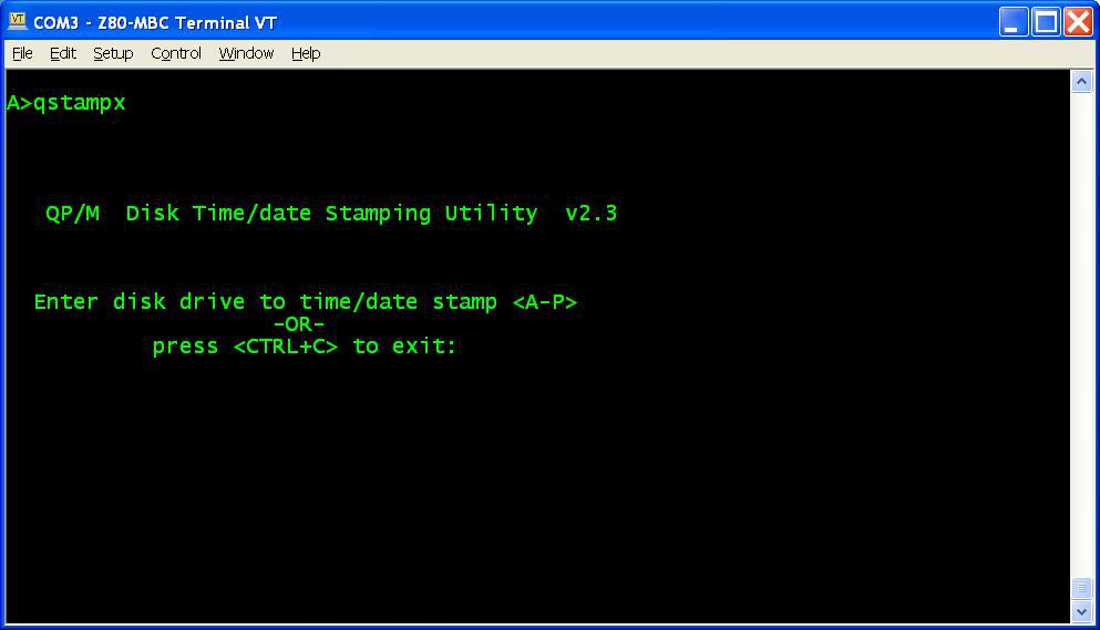 and do the "disk timestamping" for both A: and B: disks.

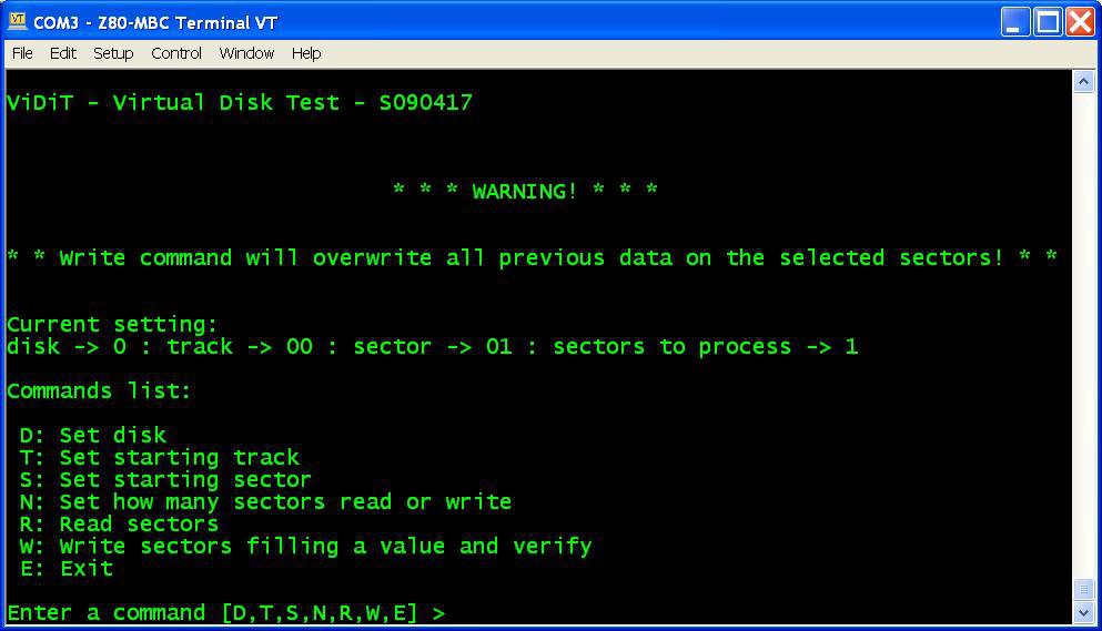
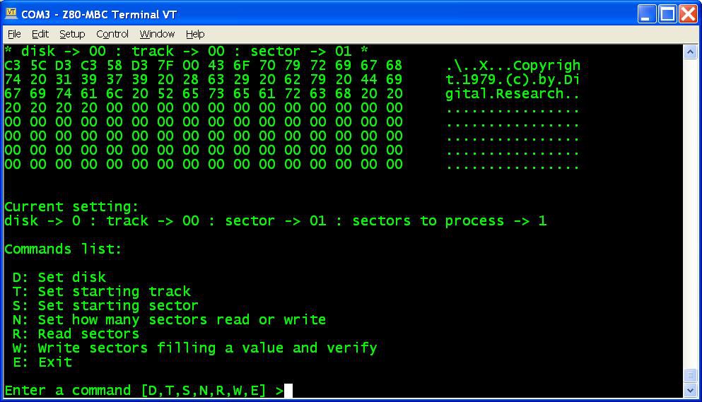
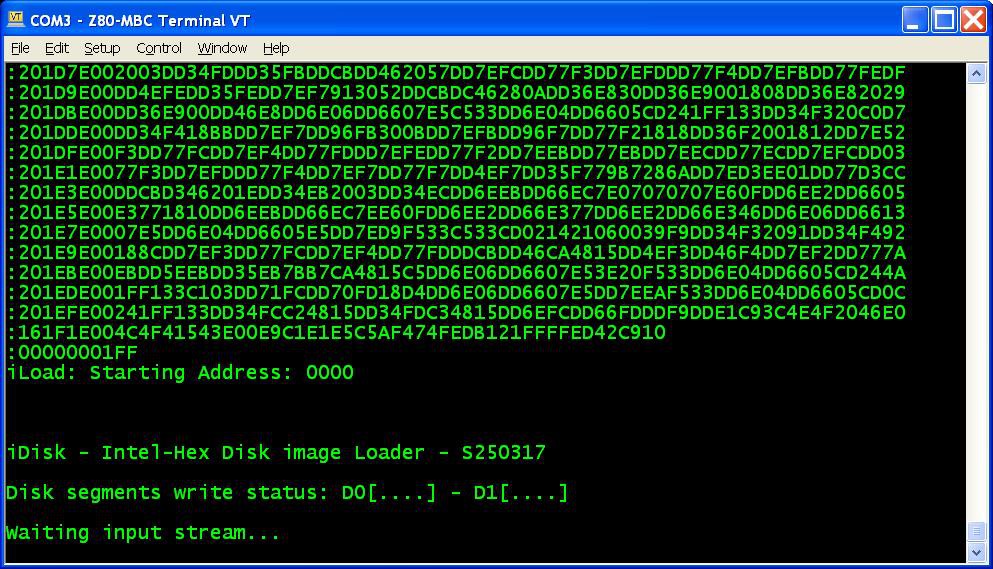 from the Tera Term menu select "File" -> "Send file..." and choice one of the unzipped .hex file from CPM22_DualDiskPack.zip (or CPM22_SingleDiskPack.zip for a single disk configuration). After the upload iDisk will show a summary:
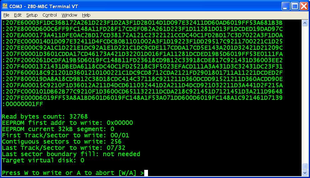 at this point press W to proceed and confirm your choice.
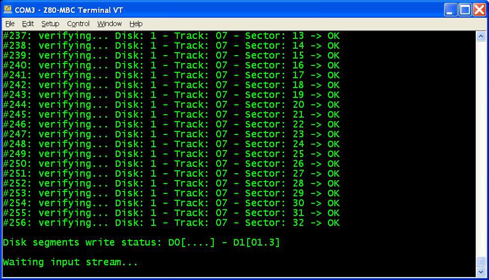 in the photo the segments 0, 1 and 3 of Disk 1 have been already successfully written, so you can choose any of the remaining;
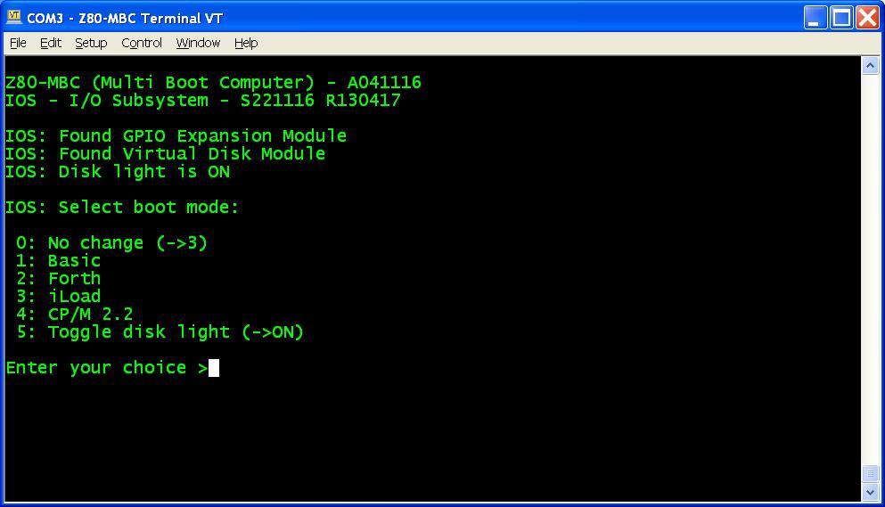 select 4 for the CP/M loader (and select the disk light ON if not already done, to have an idea of the behavior).
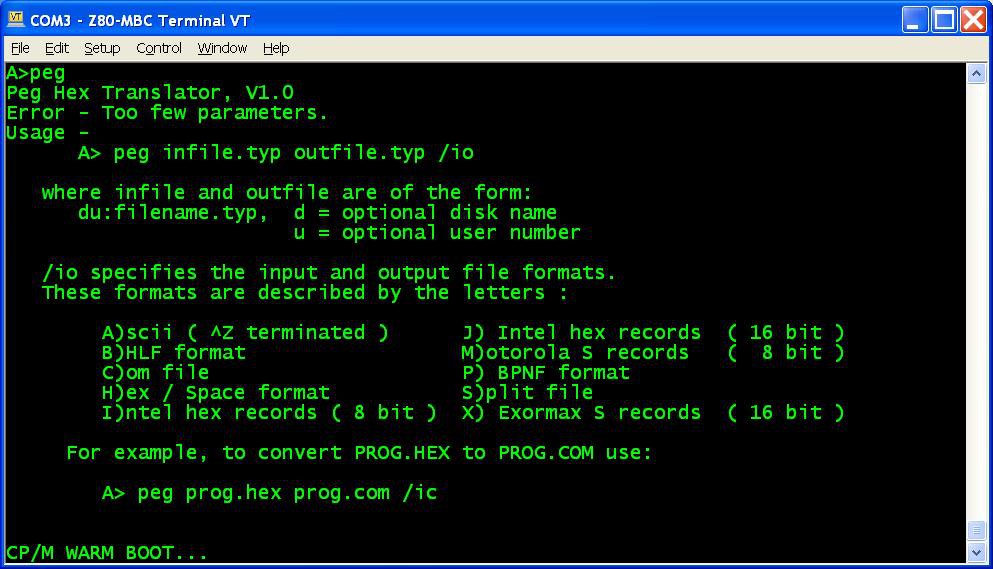
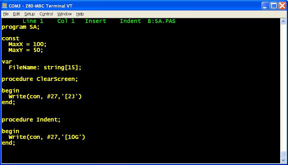 In the "single disk pack" the CP/M Assembler and the Macro Assembler are missing, and the Turbo Pascal is without the installing executable (not a big issue anyway) and without the sample program.
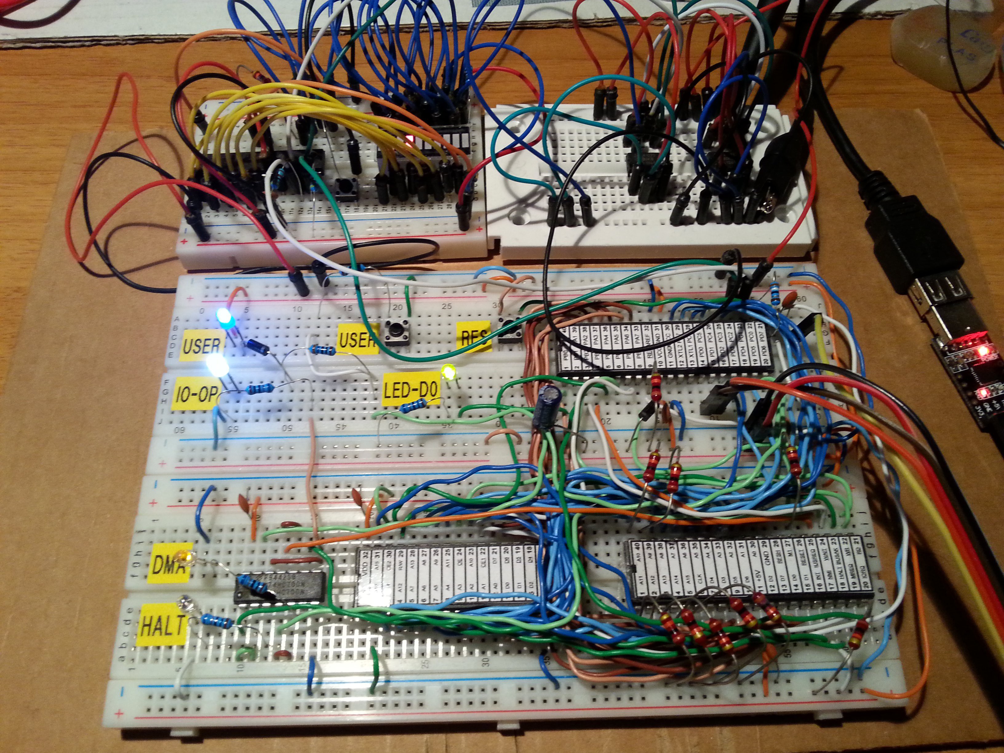


 Plasmode
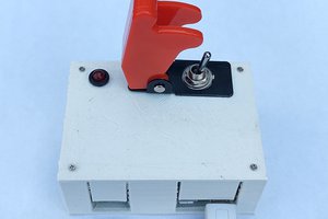
 Elbert
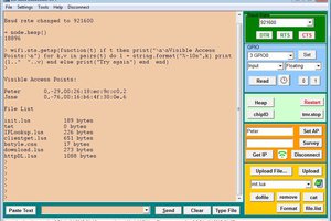
 GeoNomad
I've added Gerbers for the V2 (untested) version of the PCB; something I should have done a long time ago... https://github.com/WestfW/4chipZ80/tree/master/Gerbers-V2