 Just4Fun
Here is an interesting alternative to CP/M developed by MICROCode Consulting that supports also file timestamping, and it is 100% CP/M 2.2 "compatible".
MICROCode Consulting has released the original installation files and all the documentation in their site with the "restricted usage" condition, that means free for non-commercial use and for personal use only, so it should be ok for us. Anyway I've sent them a mail about this project.
To enable timestamping you need a DS3231 based RTC module like this one:
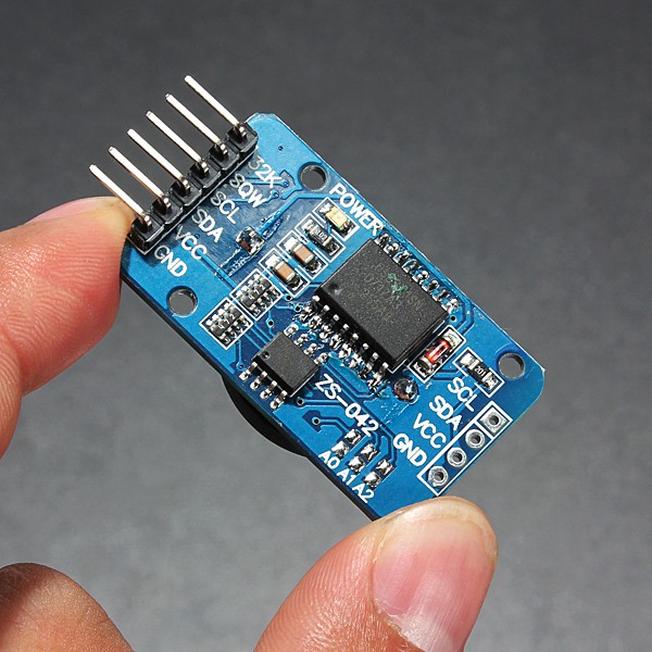
WARNING: these modules can cause battery "explosion"! How to fix it
This cheap modules have a trickle charging circuit that may cause the "explosion" of the battery if you use a standard CR2032 cell. More, it can damage also a rechargeable LIR2032 cell (see this thread). So the safer thing is "disable" the trickle charging circuit (a CR2032 can last 5/10 years, so there is no practical need to a rechargeable battery, after all...).
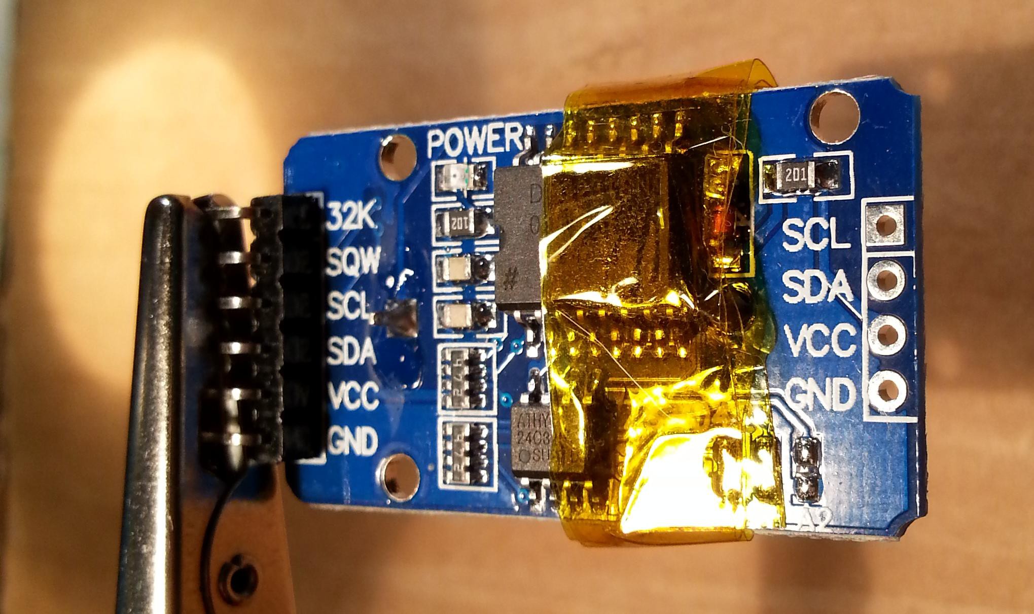
To avoid any charging current flowing into the battery you can take away the series limiting 200 Ohm resistor (or cut the trace). Alternatively you can take away the red diode, or destroy it (it is in series with the 200 Ohm resistor). In the following photo you can see the module with some Kapton tape (used as thermal barrier) before to desolder the 200 Ohm resistor (on the right marked as 201) with an hot air gun:
And here after the desoldering:
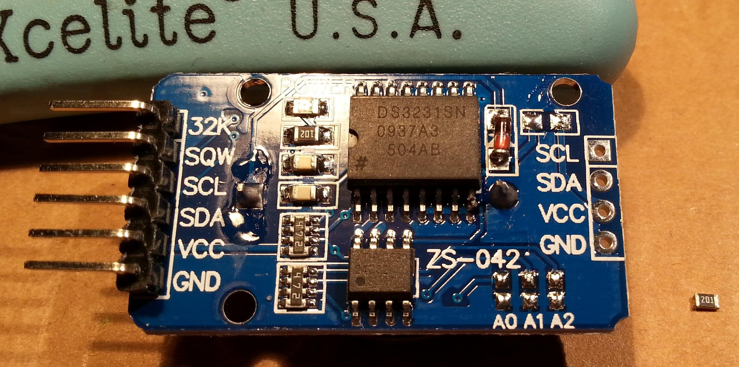
Now the module it's safe and a CR2032 can be used. To connect it use the SCL/SDA/VCC/GND terminals and connect them at the corresponding pins of the IOEXP/I2C connector of the Z80-MBC (pay attention because the position of the signals is different):
QP/M quick set up guide
The setup is quite similar to those used to install CP/M. The Assembler automated toolchain must be already set up and the Virtual Disk Module present.
Here all the steps:
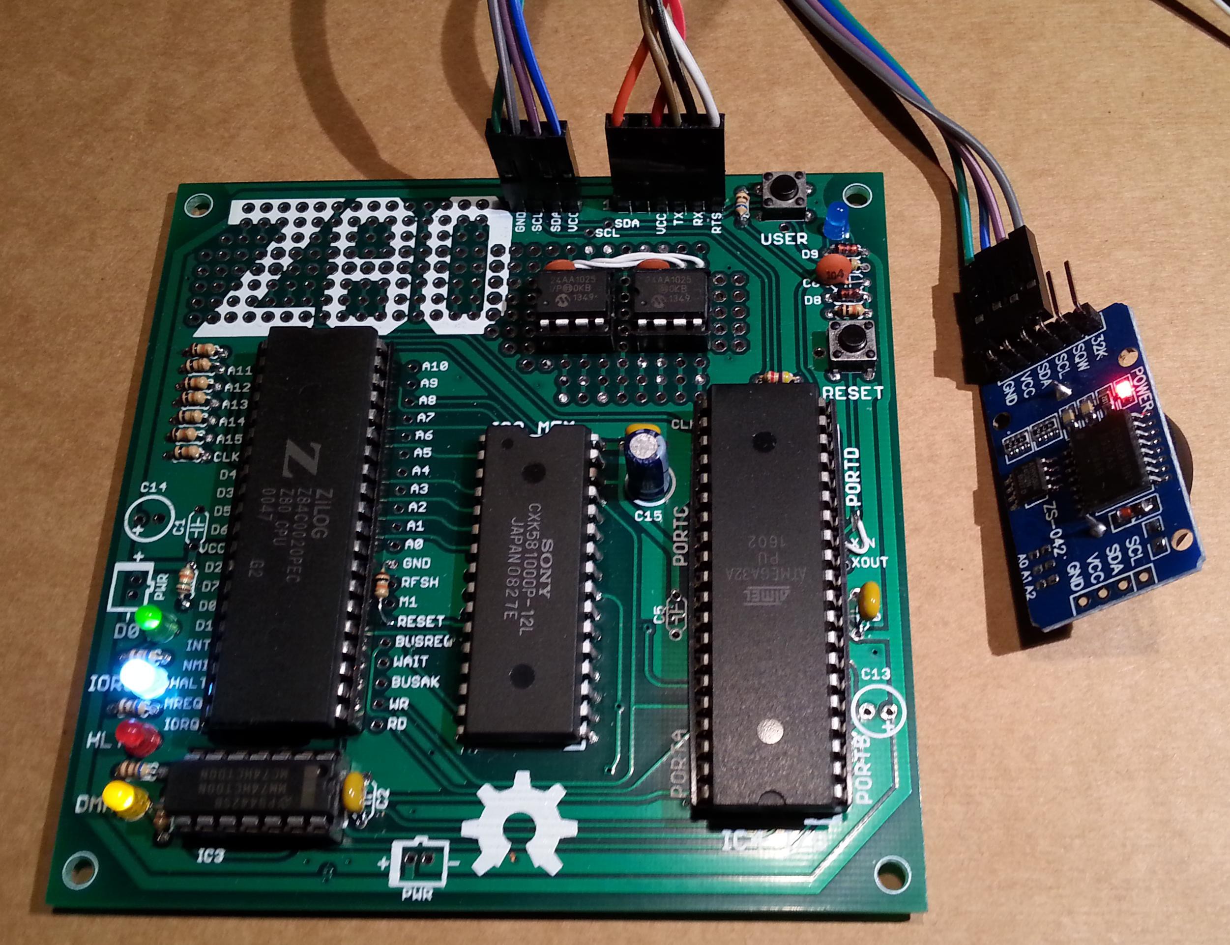
- Connect the DS3231 module (with the CR2032 battery inside);
- Update the IOS using the new file S221116_R100218_Z80.ino in the File section;
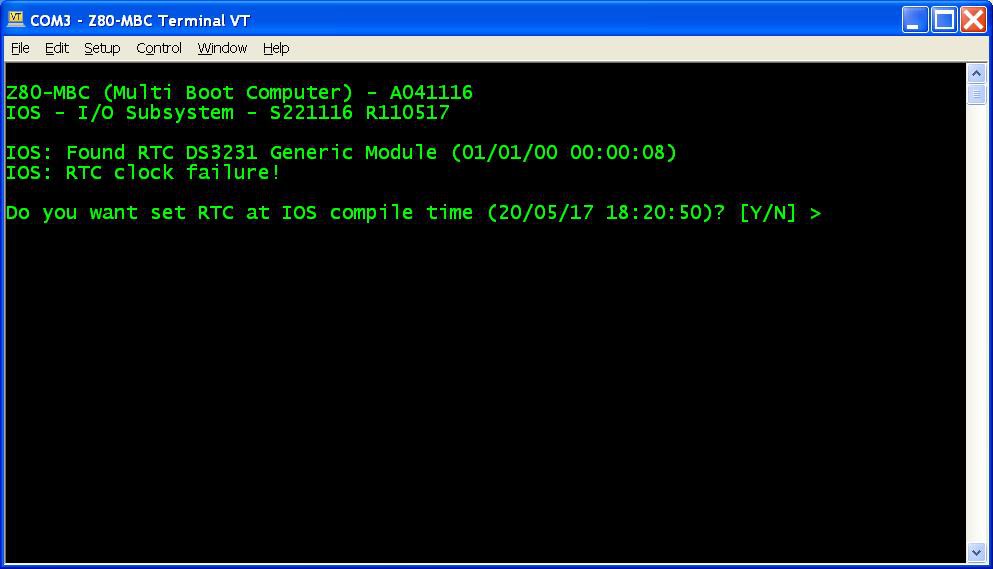
- Reboot the Z80-MBC and from a terminal emulator you'll see this:
![]() Press Y. If you are enough fast you have the RTC set up with the right date/time taken from the sketch compile time (if you are lazy like me you'll find this very handy...). In any case it is possible adjust the date/time manually too from the boot selection menu;
Press Y. If you are enough fast you have the RTC set up with the right date/time taken from the sketch compile time (if you are lazy like me you'll find this very handy...). In any case it is possible adjust the date/time manually too from the boot selection menu; - Reboot the Z80-MBC again and select the iLoad boot mode;
- From the File section download the file "QPM271_DiskPack.zip", unzip it in the directory used for the Assembler automated toolchain;
- Upload the file "iDisk - S250317.hex" to the Z80-MBC using the Dos batch L.BAT (see Assembler automated toolchain) with the command:
L "iDisk - S250317.hex" - When iDisk waits for the input stream, from the Tera Term menu select "File" -> "Send file..." and choice one of the unzipped .hex file from QPM271_DiskPack.zip;
- Repeat step 7 for all the four files;
- Press the Reset button on the Z80-MBC and enter into the boot selection menu and select 4 to load the OS from disk 0 (and select the disk light ON if not already done, to have an idea of the behavior):
![]()
 Press Y. If you are enough fast you have the RTC set up with the right date/time taken from the sketch compile time (if you are lazy like me you'll find this very handy...). In any case it is possible adjust the date/time manually too from the boot selection menu;
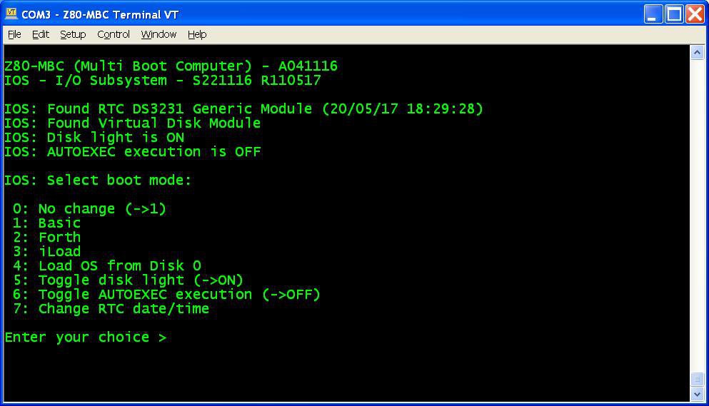
NOTE: as already noticed, if you experience errors during the serial upload increase the delay after each line from the Tera Term menu (Setup -> Serial port -> Transmit delay -> msec/line). In my VM I set up a 90ms delay. This is due because Arduino serial port doesn't have any handshaking.
Now you have QP/M 2.71 up and running, but you need further operations to enable the file timestampig (as stated in the QP/M Installation Guide):
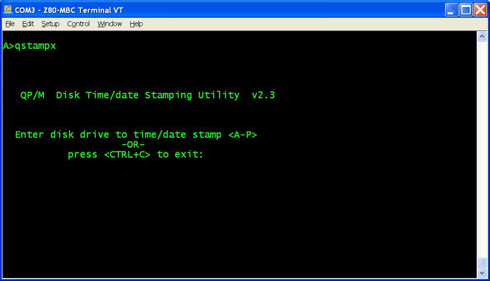
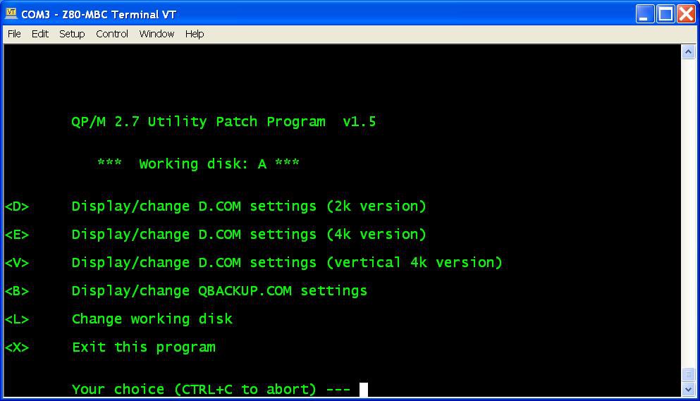
- To enable file disk timestamping it is necessary run the utility QSTAMPX from A:
![]() and do the "disk timestamping" for both A: and B: disks.
and do the "disk timestamping" for both A: and B: disks.
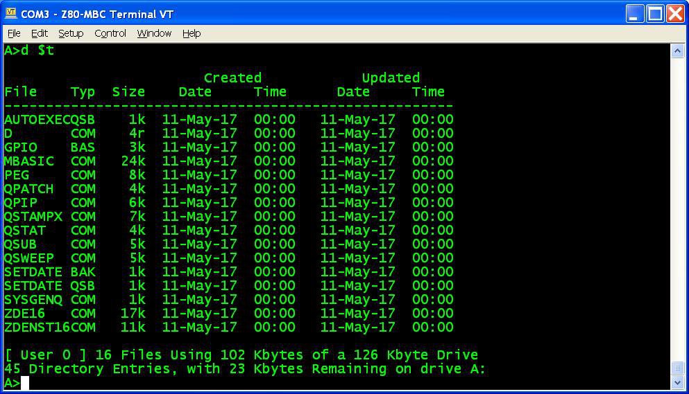
When done type the command D $T and check that the output is similar to this:![]()
- Now to set up a starting date to all files give the command QSUB SETDATE to run a simple batch that I made to do this initialization easily;
- Copy the file SETDATE.QSB to drive B: (using the command QPIP B:=SETDATE.QSB) and repeat from B: the same batch (QSUB SETDATE). Now the command D $T will give this output:
![]()
 and do the "disk timestamping" for both A: and B: disks.
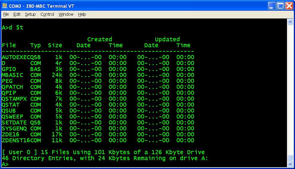
All done!
It is possible setup the D command to display the timestamping as default mode. To do this give the command (from A:) QPATCH:
select the E option, then the option 5, and X to save. Repeat this for both disks and exit the QPATCH program. Now the command D will give the output with file timestamping without specify any option.
In the Files section you can find the BIOS source "BIOS QPM271 - S080517.asm". The only change (compared with the CP/M BIOS) is the RTC routine.
The Cold Loader is the same used for CP/M.
I suggest to read the QP/M documentation for the various commands (see the Downloads section in their site).
AUTOEXEC
The QP/M uses for the batch file the .QSB extension. So the AUTOEXEC file is now renamed AUTOEXEC.QSB. To enable the AUTOEXEC execution after the cold boot change the corresponding state to ON from the usual IOS boot selection menu.
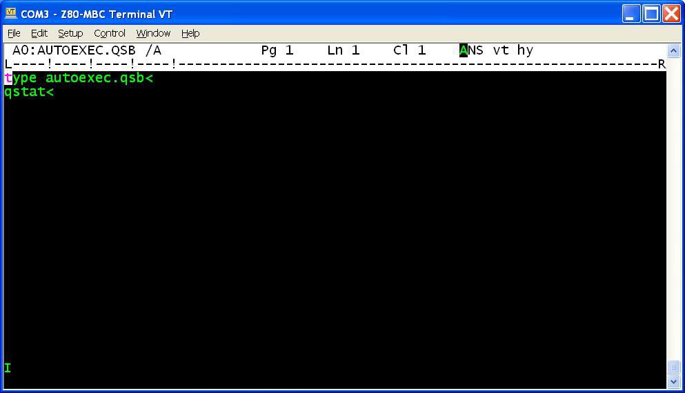
In the QP/M "disk pack" (QPM271_DiskPack.zip) there is an example of AUTOEXEC.QSB file.
ZDE editor
I've added a screen oriented text editor: ZDE16. For more information see this site.
About the I2C pullup
The RTC module has it's own pullup resistors on SDA and SCL. Because the value is 4k7, the resulting value will be:
4k7 // 4k7 = 2k3
Because this value is fine there is no need to take away the pullup on the RTC module.
If you used different values on the Z80-MBC, you must check that the resulting value is not less than 1k8 (taking some margin). If so, take away the pullpup resistors on the RTC too.
Discussions
Become a Hackaday.io Member
Create an account to leave a comment. Already have an account? Log In.