 Bharbour
This board is used to control the discrete LEDs that are on the front of the display. Those LEDs are combined Red and Green LEDs so they control much the same as the matrix LEDs for the character displays.
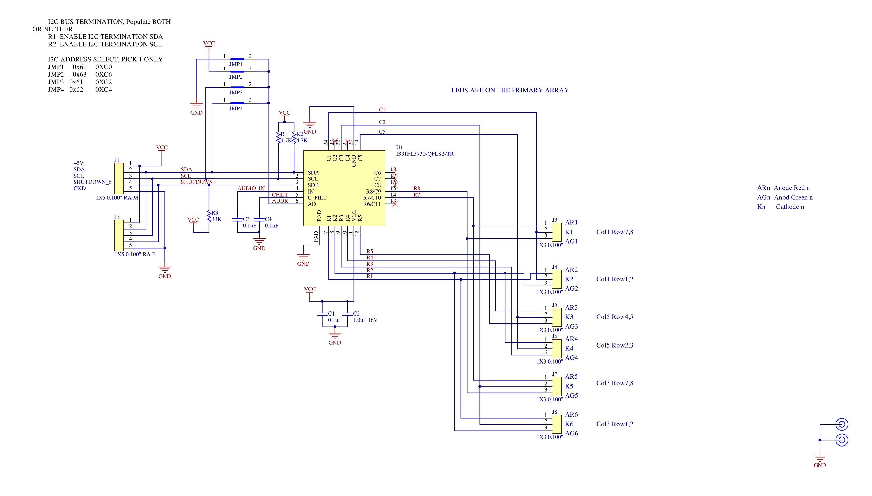
This board uses the same driver chip (IS31FL3730) that the character driver boards use, but only makes use of a few of the possible LEDs.
Two connectors with the same pinout as the character driver boards would allow this board to be plugged into one of the matrix LED driver boards, if the I2C addressing allowed. The I2C address is set via a jumper up in the upper left part of the schematic. In this project, there are not enough I2C address choices to put this board on the same I2C bus as the character driver boards, so it is not run as a pass through board. Software to control this board is derived from the software that controls the character driver boards.
The discrete LEDs are mounted on small boards with space for a mounting screw and a 1x3 2.54mm connector. In practice, I have just been soldering wires into these boards and putting the connectors on the end of the cables that plug into the Miscellaneous LED Control board.
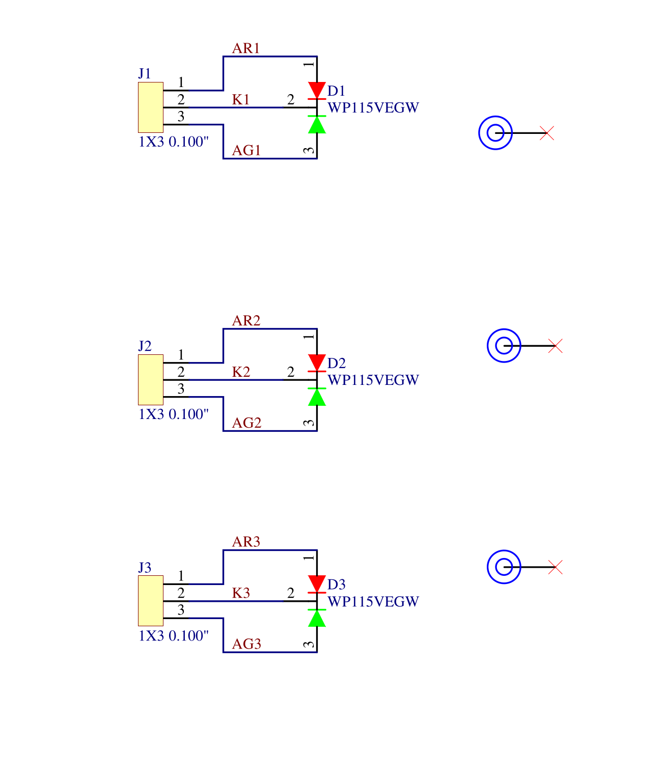
There are 3 sets of LED, connector and bolt hole per "board". This is a crude panelization on my part. When I get the boards in, I cut them apart on the bandsaw. Most projects use a number of these boards, so getting them 3 at a time is good. This project uses 5 of these lndividual boards.
Discussions
Become a Hackaday.io Member
Create an account to leave a comment. Already have an account? Log In.