 Bharbour
This board design has been through numerous iterations, some for ease of use, some for cost reduction. Details can be found in my #LED Matrix Display project.
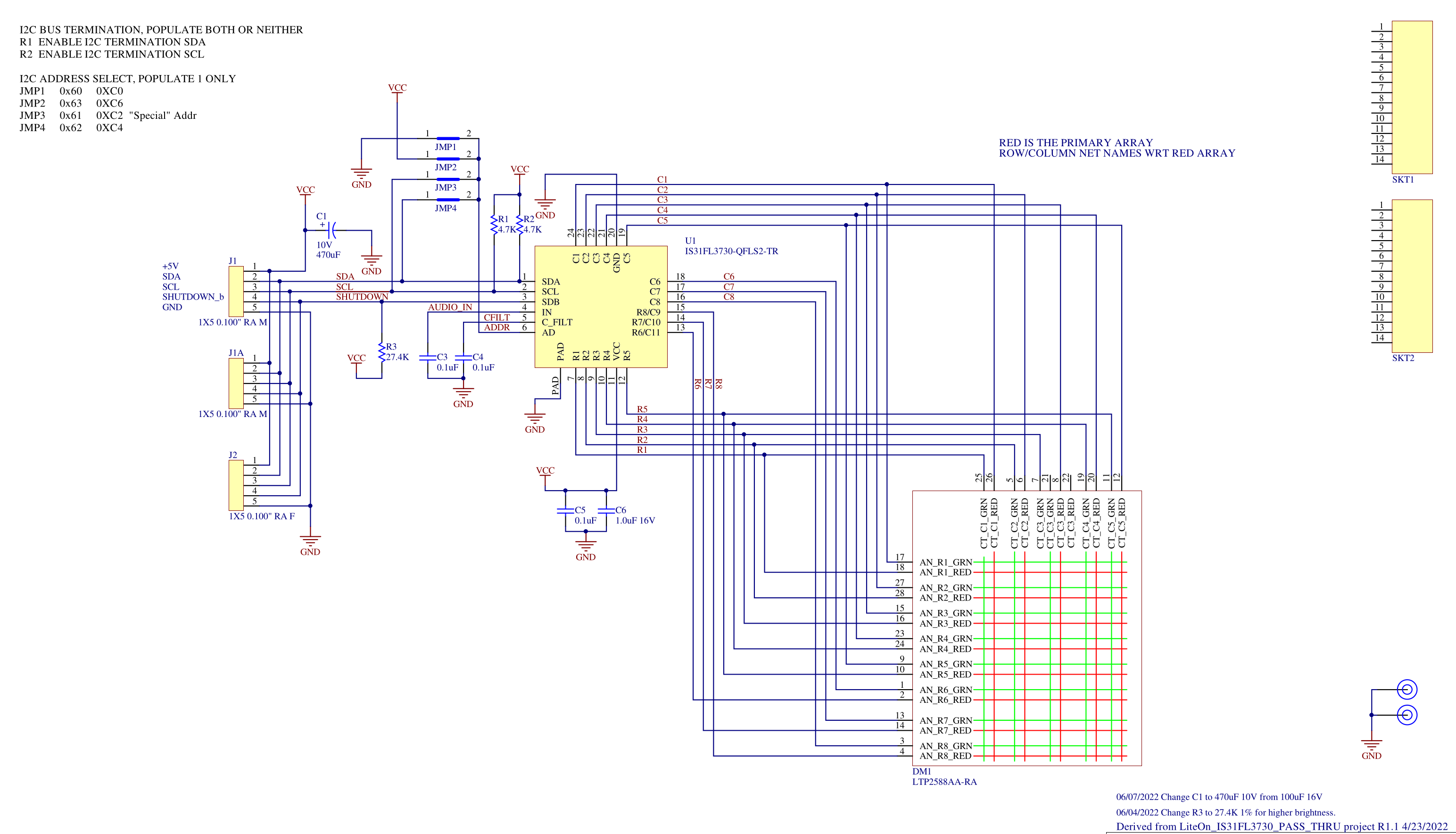
The IS31FL3730 chip drives the character matrix LED modules via I2C commands. Full control of all the connected LEDs including intensity is possible. Selecting a RED or Green character is also possible. The chips are pretty inexpensive at $1.20 each in quantities of 10. The LED matrix modules (LiteOn LTP2588AA) come from a local electronic surplus place. The LED matrix modules have Red and Green LEDs at each location.
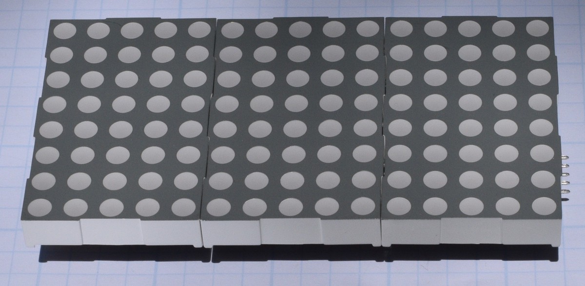
These boards can be stacked next to each other with up to 4 modules on the same I2C bus or segment. They can be assembled to have the LED modules in contact with each other for a continuous matrix of LEDs, or to have a physical gap between the LED modules. Here is an example of 3 boards built with the displays in contact with each other.
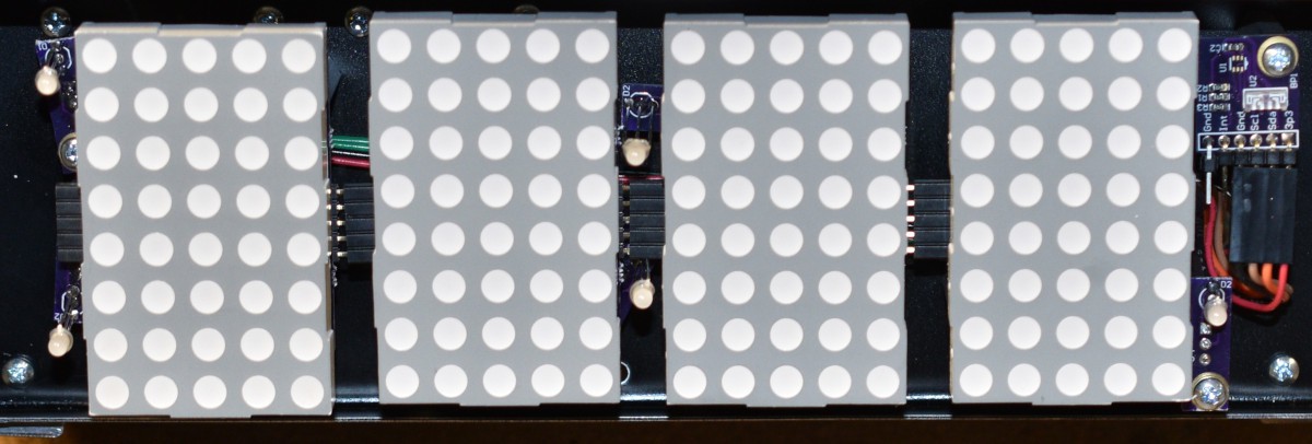
Having the physical gap between the LED modules allows you to get 1 character per module. The continuous matrix configuration lets you get 4/5ths of a character per matrix, so you would need 5 modules for 4 characters. This is because the characters are 5 columns wide by 8 columns tall, and you need at least one column of blank space between characters. The driver software becomes significantly more complex for the the continuous matrix configuration too. The plus side of the continuous matrix is that if you are scrolling characters across it, the continuous matrix looks a lot better. Using the physical gap between characters looks kind of jerky when scrolling. This point is moot in this project though since there is no scrolling. Things moving in my peripheral vision is extremely distracting to me, so scrolling displays were never considered for this project. Here is an example of 4 boards built with the physical gap between the displays.
Individual LEDs are controlled by the chip scanning rows and columns, so individual LEDs are switching on and off rapidly. This results in pretty sharp edges in the power supply current waveform. Originally, I had 2 10uF ceramic capacitors on each display module and it functioned, but looking at the waveform, I suspect it contributed to conducted emissions of EMI quite a bit. I replaced the two 10uF ceramic caps with one 470uF electrolytic cap, which helped slow the edges down, but I suspect the frequencies are too high for an electrolytic cap to fully solve.
Discussions
Become a Hackaday.io Member
Create an account to leave a comment. Already have an account? Log In.