 Bharbour
This board accepts a low frequency ( < 1KHz ) square wave from a timer on the MCU,converts it to a triangle wave and amplifies it to drive a speaker.
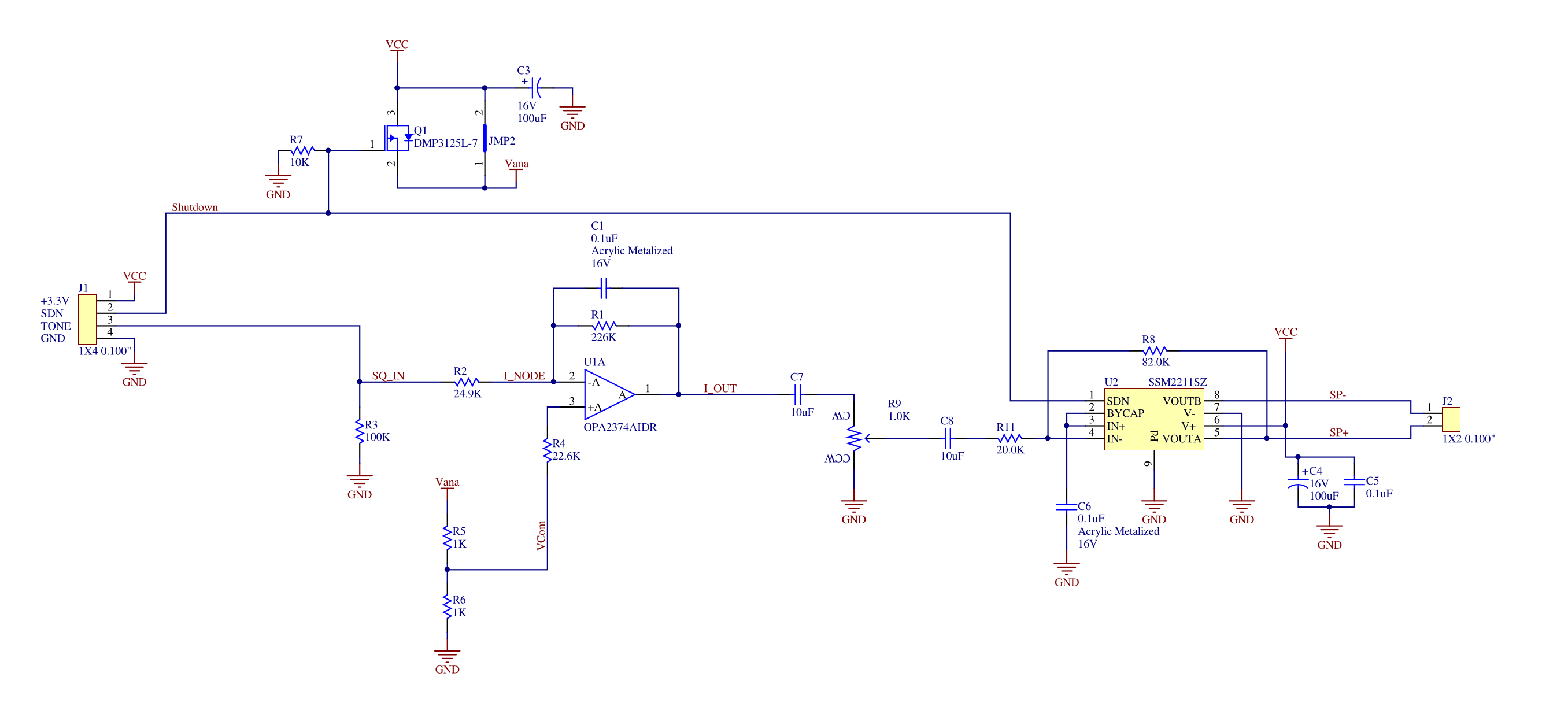
When I designed the board, I was not sure how cleanly the integrator would start up when the square wave input begins, so I included hardware to turn off power to the opamp in the integrator. The first board got built with Q1 not populated and JMP2 populated, which leaves the integrator powered all the time. With a little testing, it looks like the integrator starts up cleanly and the output voltage moves down to be centered around the 50% VCC point within a few cycles. The Integrator output is AC coupled to the volume control R9, so there is no DC current as a result of the integrator output sitting at 1.8V.
Similarly, the input to the speaker driver chip U2 is AC coupled to the volume control so the input to the speaker driver chip floats around 1.8V too. The shutdown signal on the speaker driver switches the amp on and off with very little clicking and popping.
At this point, I am planning on leaving the tone output from the MCU running all the time, and enable the sound output by negating the shutdown signal to the amplifier.
The triangle wave out of the integrator looks very clean on an oscilloscope. It sounds pretty good too.
This is the last of the boards going into this design.
Discussions
Become a Hackaday.io Member
Create an account to leave a comment. Already have an account? Log In.