Jelle Reith
This project was born out of my fascination with Sharp's memory LCD and my aspiration to showcase three-dimensional visuals on this remarkable display. The software responsible for generating the 3D world displayed on the screen draws inspiration from Tim Clarke's 'Mars Demo' created back in 1993—a revolutionary piece of software that was far ahead of its time.
In my quest to understand the inner workings of the 'Mars Demo,' I dived into research papers and stumbled upon the work of Mark Feldman, who had programmed it in Java. Utilizing Feldman's code as a reference, I started programming it for the ESP-32 S3 microcontroller. However, I struggled a lot trying to run it at high FPS and the program became a trade-off between terrain detail and processing speed.
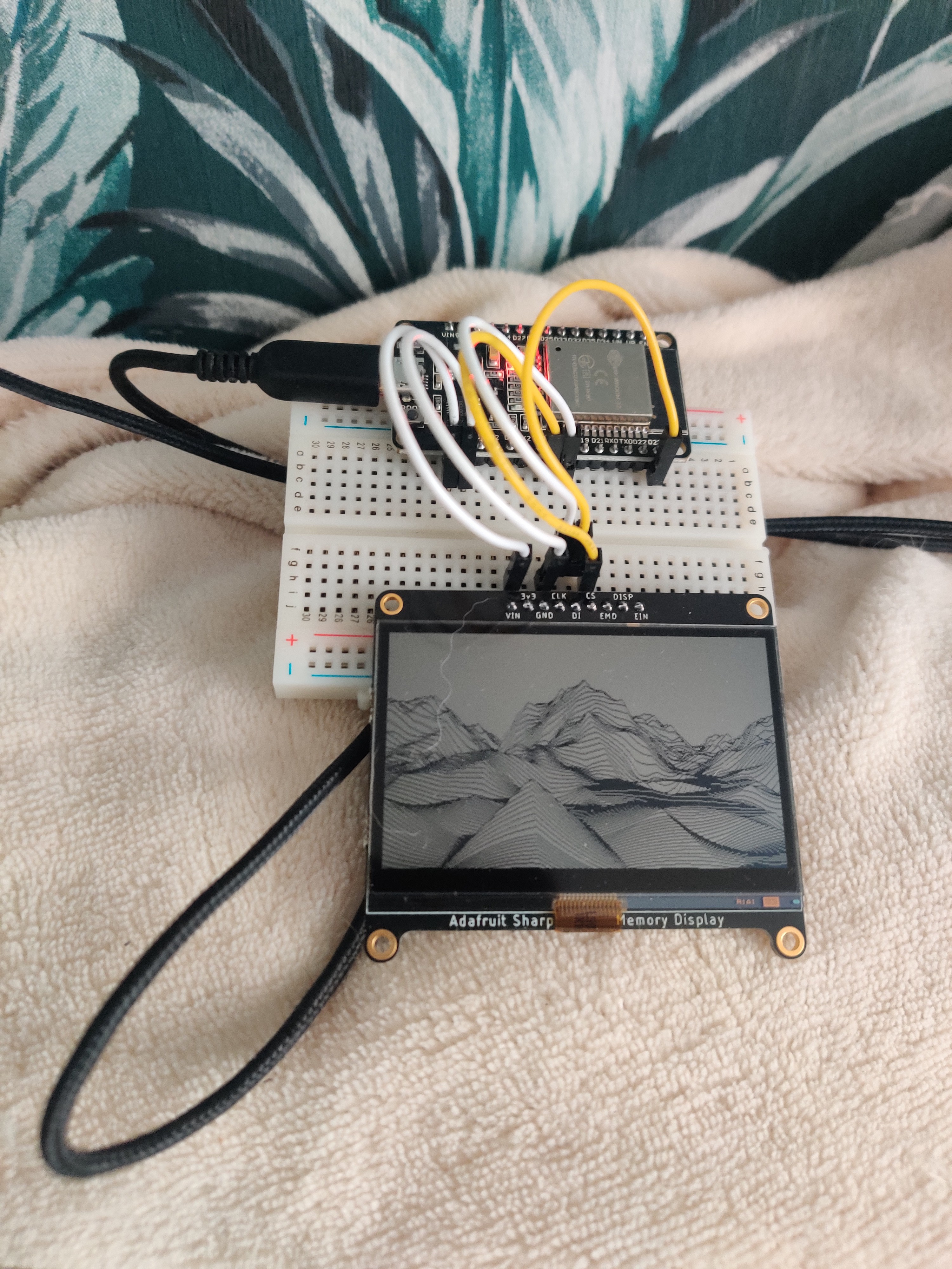
My first crude test looked like this. Later I switched to the ESP-32 S3 because its a tiny bit faster.
After spending a lot of time trying to crank out as much frames per second I decided to try to maximizing the runtime of the art piece. This led me down into an interesting rabbit hole of low-power electronics and effecient programming.
There are a few things that I learned through making this project. One of those things is about the different sleep-modes of the ESP-32. When the ESP-32 is in light-sleep mode, the volatile memory responsible for storing the world remains active, ensuring that the generated world is preserved upon waking up. However, when the ESP32 enters deep-sleep mode, the volatile memory is lost so it is necessary to stpre the current world parameters within non-volitile memore necessitating the saving of current world parameters to non-volatile memory prior to entering deep-sleep.
Here's the interesting twist: saving the world parameters takes some time and uses a bit of energy. Therefore, the decision to save the world parameters becomes worthwhile only when the microcontroller remains in deep-sleep mode for an extended period, allowing the energy savings to offset the cost of saving the parameters. For those who are interested; for my particular program it became beneficial to use deep-sleep when sleeping for more than 4500 milliseconds.
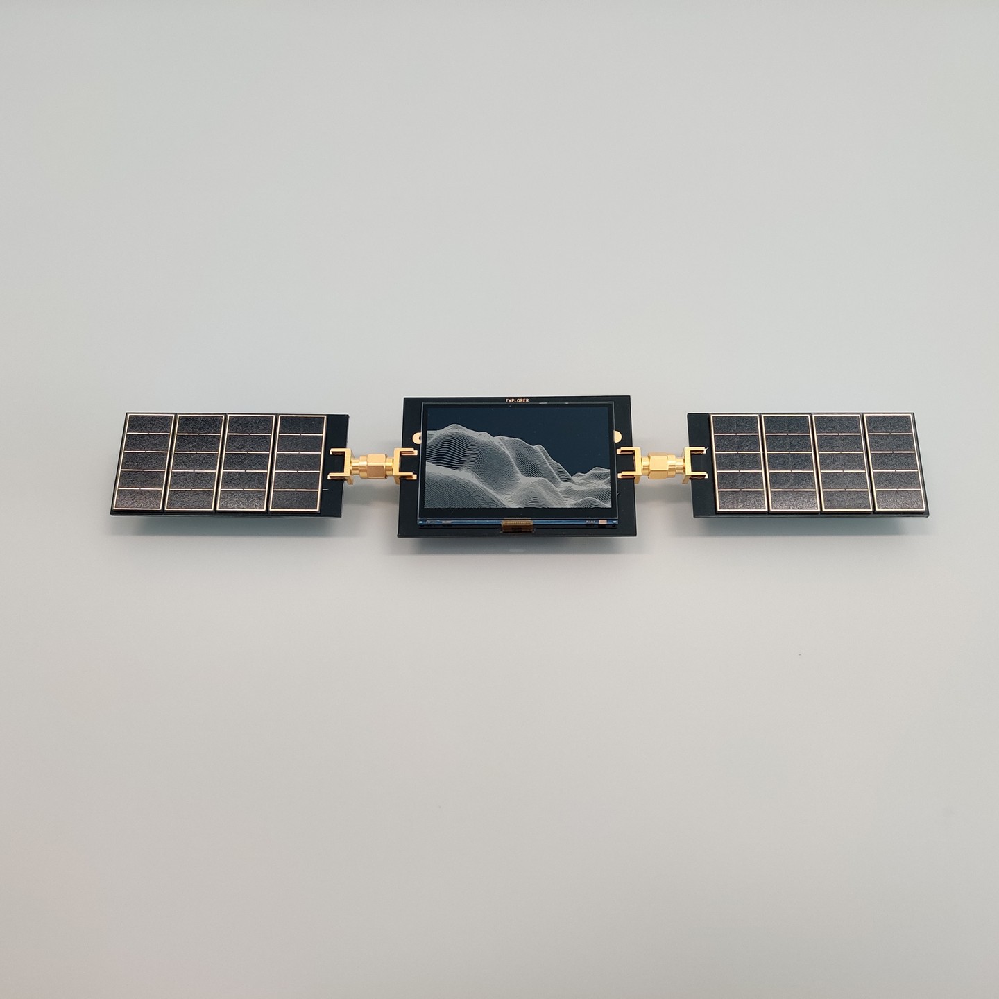
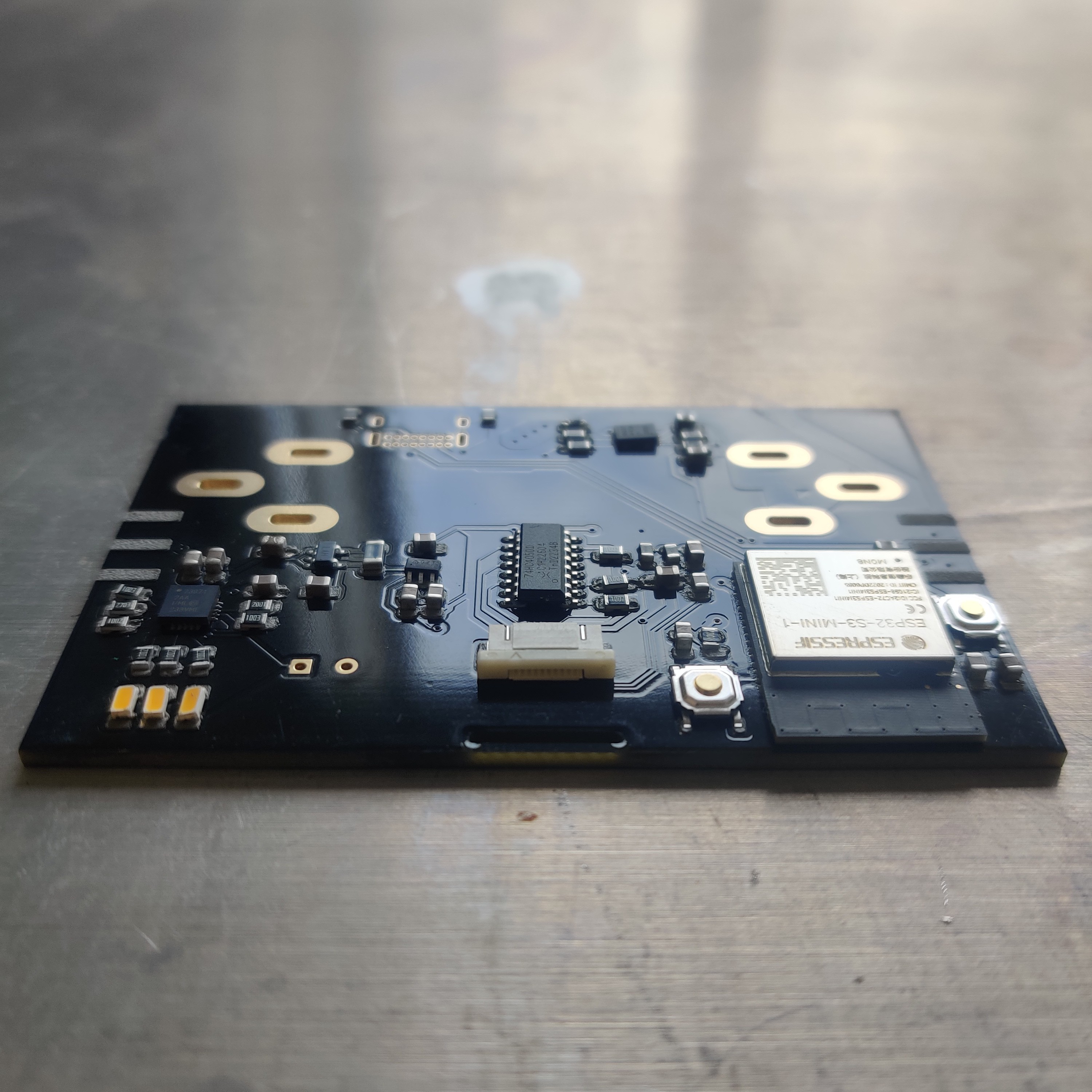
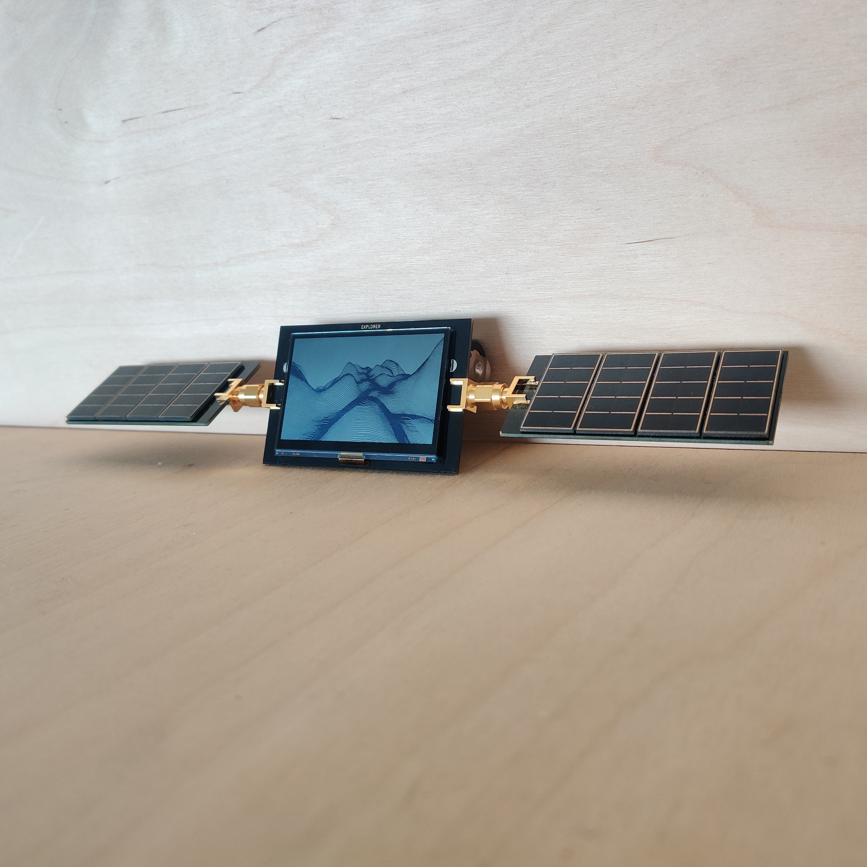
On the hardware side of things there are only four major parts to the device: It is using the ESP-32 S3 MINI chip as its main processor. The MCP73871 Li-ion charge uses solar energy to charge the li-ion battery. The battery voltage is converted to 3.3v using a ADP2108/AP2112 . Lastly there is the bq27441 fuel-gauge that keeps track of the battery's SOC and feeds that data into the ESP-32. The fuel-gauge chip also provides me with some hand-dandy power measurements and is showing when the battery is being charged by sunlight.
When doing one frame per second the chip tells me that the whole system is using 14 milliamps at 4.1V which translates to a power consumption of 57 milliwatts. The Li-ion battery that I'm using stores a total of 12.95Wh so it should last for about nine days. I currently have not been successful at measuring the power consumption at one frame per hour since the bq27441 chip can only average its readings for one second so for this we have to do some calculations. When the ESP32 is active I measured its current draw at close to 70mA (at 3.3v). This means its using about 0.23 Watts, or 230 milliwatts. It takes the ESP32 approximately 60 milliseconds, or 1.67e-5 hours, to execute the code that renders the frame on the display. If we multiply the power consumption (0.23 Watts) by the amount of time using it (1.67e-5 hours) we know that it costs the ESP32 about 3.85e-6 Watt hours to calculate one frame. In light-sleep mode the ESP32 consumes 2.64e-3 Watts so during its almost one hour long sleep it will consume 2.64e-3 Watt hours. This means the power used to render the frame is also negligible compared to the power used to sleep.
To calculate the expected battery life we also need to factor in the power consumption of the fuel-gauge, display, charger-ic and the LDO. The fluke 175 that I used to measure the current has a accuracy of 1% +-3 milliamps so it's utterly useless at measuring small currents so we just have to trust the datasheets here. According to the datasheet the Sharp Memory Display uses 50uW when not updating the image. The fuel-gauge uses 93uA when in normal operating mode, the battery charger ic uses 28uA when in standby mode. At 3.3v working voltage the fuel-gauge and charger ic add up to 0.42 mW. The LDO also consumes some power. The power lost with the LDO can be calculated by multiplying the difference in input and output voltage, 0.8v, by the current that is flowing through the device (0.8mA) so the power lost in the LDO is about 6.4mW. The total power consumption of the fuel-gauge, charger ic, display and the LDO add up to 6.82mW. The LDO wastes the the most energy and causes the battery to drain in about 58 days.
First prototype!
Thanks to Sjoerd Mol who made the amazing cloud background. --> https://sjoerdmol.com/Wolkenzicht
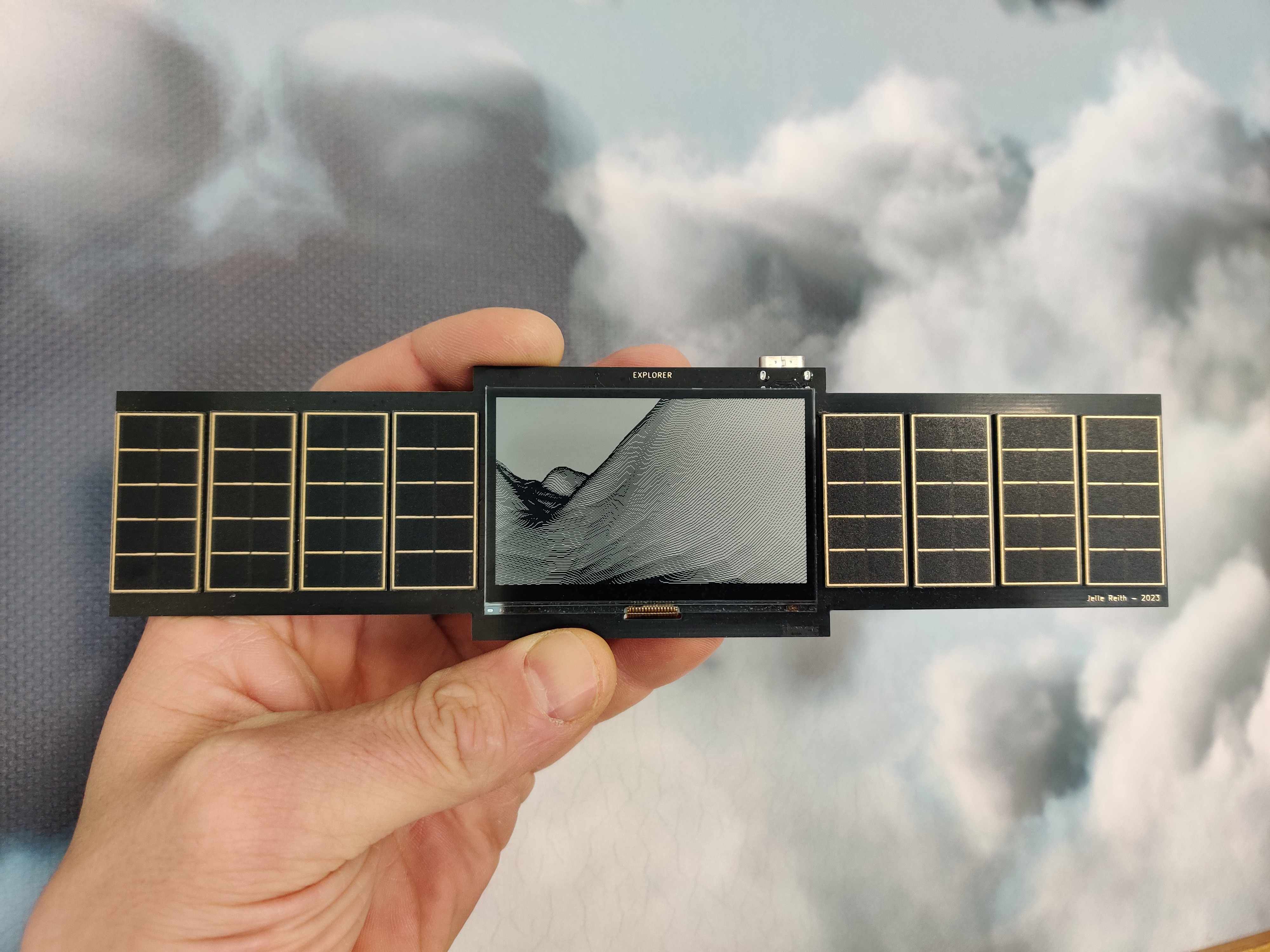
Update V2
After publishing V1 PCBWay reached out to me because they wanted to sponsor this project! This was a very welcome offer since there were some things in the first version that I needed to change. In the new version I replaced the LDO with a more efficient buck converter (more on that later). In addition I also made the solar panels separate and connected them with a edge launch SMA connector so that the can be rotated. PCBWay has a addon for KiCad which makes it very easy to order new PCB's. I was keen to test that out and it worked very well. In my KiCad design there are three PCB's, the main pcb and two solar panel PCB's. The PCBWay export button didn't have trouble exporting the files which was very nice! The engineers at PCBWay looked over the design checked with me if all was well and they started the production of the PCB's right after. Within 7 days I already received the new PCB's and they turned out glorious! The silkscreen is a very deep dark black with a perfect shiny finish which goes perfectly with the beautiful ENIG gold plated surface finish. Thanks PCBWay!

After receiving the new PCB's I started testing the new design and a few fun problems for me to deal with popped up. First being the voltage ripple that was too big for the ESP-32 to work properly. A simple (golden) 1000uF capacitor on the output fixed the problem. The second problem still has to be dealt with. After a few days of use the device shuts down. The buck converter seems to just stop working and needs a complete power cycle in order to work again. Right now I'm testing if the buck converter is really that much more efficient than the LDO. I got two Explorer devices running identical code and I'm monitoring the battery voltage over a few days of use. If it turns out that the buck converter is not that much more efficient that the LDO I might switch back to a LDO again. As of this moment the battery voltage of the device utilizing the LDO is at 4.065v where the buck converter powered device has a battery voltage of 4.060v.
Code wise I also made a few improvements. I implemented a way for Explorer to use deep-sleep. At reset a height map of the world is generated and it is saved in SPIFFS. After waking up from deep-sleep the world is loaded from SPIFFS again. It takes the ESP-32 about 162ms to load the world from SPIFFS and when the sleep time is more that 4165 milliseconds it starts to be beneficial to use deep-sleep over light-sleep.
After spending a few months testing both the Buck converter and the LDO it turns out the Buck convertis isn't more efficient that the LDO. I made a setup with two Explorers, one with the LDO and one with the Buck converter and I monitored the voltages from both batteries. Initially battery of the LDO powered device was draining the fastest. At higher voltages the buck converter is indeed more efficient that the LDO. However, while the battery voltage was dropping the LDO became more efficient at converting the voltage. This happens because the power lost over an LDO is related to the difference in input and output voltage. After the thirteenth day of testing both battery had the same voltage and after the fourteenth day the device with the LDO had a 4 millivolt higher potential than the device with the buck converter.
I ran the same experiment again swapping out the batteries to ensure that it wasn't a problem with the batteries and this yielded similar results. This caused me to change back to the original PCB design with the LDO instead of the buck converter.