 mircemk
Roulette is a casino game named after the French word meaning little wheel which was likely developed from the Italian game Biribi. In the game, a player may choose to place a bet on a single number, various groupings of numbers, the color red or black, whether the number is odd or even, or if the numbers are high (19–36) or low (1–18). To determine the winning number, a croupier spins a wheel in one direction, then spins a ball in the opposite direction around a tilted circular track running around the outer edge of the wheel.
There are two popular roulette wheels: American and European. The European wheel has only one zero while the American wheel has two zeroes. Also the number sequence is different.
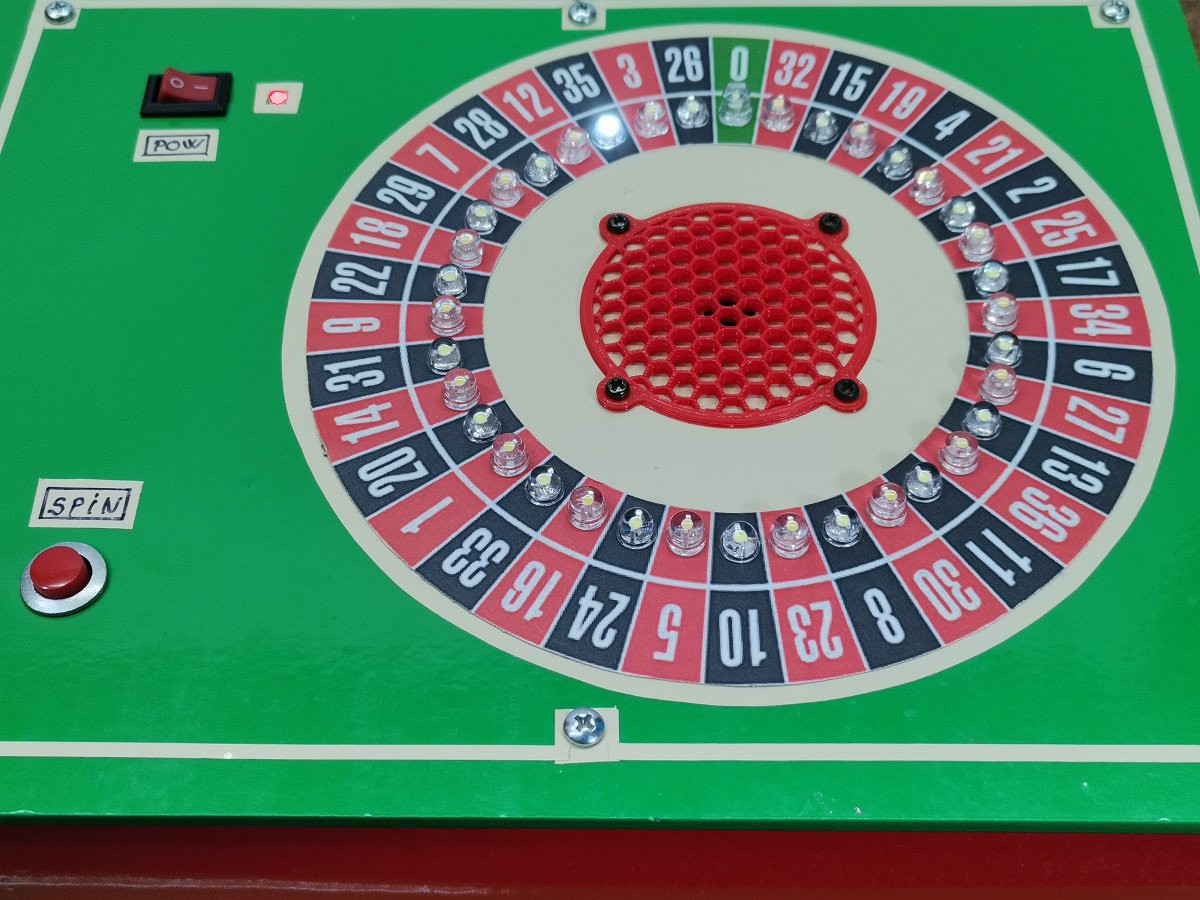
This time I will present you how to make an electronic version European roulette, where the movement of the ball is simulated by successive lighting of LEDs.
Note that you can see the original project at "www.theohupkens.nl/English/RouletteWheel.html" and I have only slightly modified the code by adding another level of spin duration. In one of my previous videos () I also presented Arduino Roulette, but it was much more complicated and difficult to make.
This time is used the Charlieplexing technique, also known as tristate multiplexing, reduced pin-count LED multiplexing, complementary LED drive and crossplexing. This is a technique for driving a multiplexed display in which relatively few I/O pins on a microcontroller are used to drive an big array of LEDs.
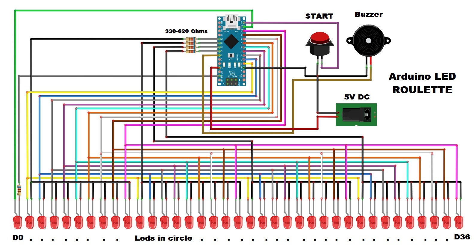
Thanks to this technique, the 74HC595 shift registers are omitted this time and the device is incredibly simple to build. It contains only a few components:
- Arduino Nano microcontroller
- 37 Leds
- five resistors
- Button,
- and Speaker
A few words about the way of connecting the diodes. The first diode is connected directly to the D11 pin and ground through a suitable resistor. The remaining 36 diodes are divided into 4 groups of 9 diodes. The cathodes of each group through a resistor are connected to A1 to A4 analog pins. The anodes of each group are connected sequentially (for example: Led2, Led11, Led20, Led29 together and connected to D2 pin of Arduino) and those 9 terminals are connected to D2 to D10 pins of the Arduino.
If you want to make a PCB for this project, or for any other electronic project, PCBway is a great choice for you. PCBway is one of the most experienced PCB manufacturing company in China in field of PCB prototype and fabrication. They have a large online community where you can find a Open Source projects, and you can also share your project there. From my personal experience I can tell you that on this community you can find many useful projects.

Now let's see how the device works in reality:
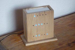
After startup four leds will rotate for a short period of time. After starting, four LEDs will rotate for a short period of time, after which one diode will remain lit. To turn the ball (LED) we have to press the button and the moment we release it the game starts. There are three levels that regulate the duration of the ball spin. If the button is pressed for less than 0.5 seconds, the rotation speed is the lowest, from 0.5 to 5 seconds the rotation speed is normal, and finally if we keep the button pressed for more than 5 seconds, it will take a minute and more to stop the ball.
During the whole time while the ball is moving, a characteristic sound is emitted through the speaker.
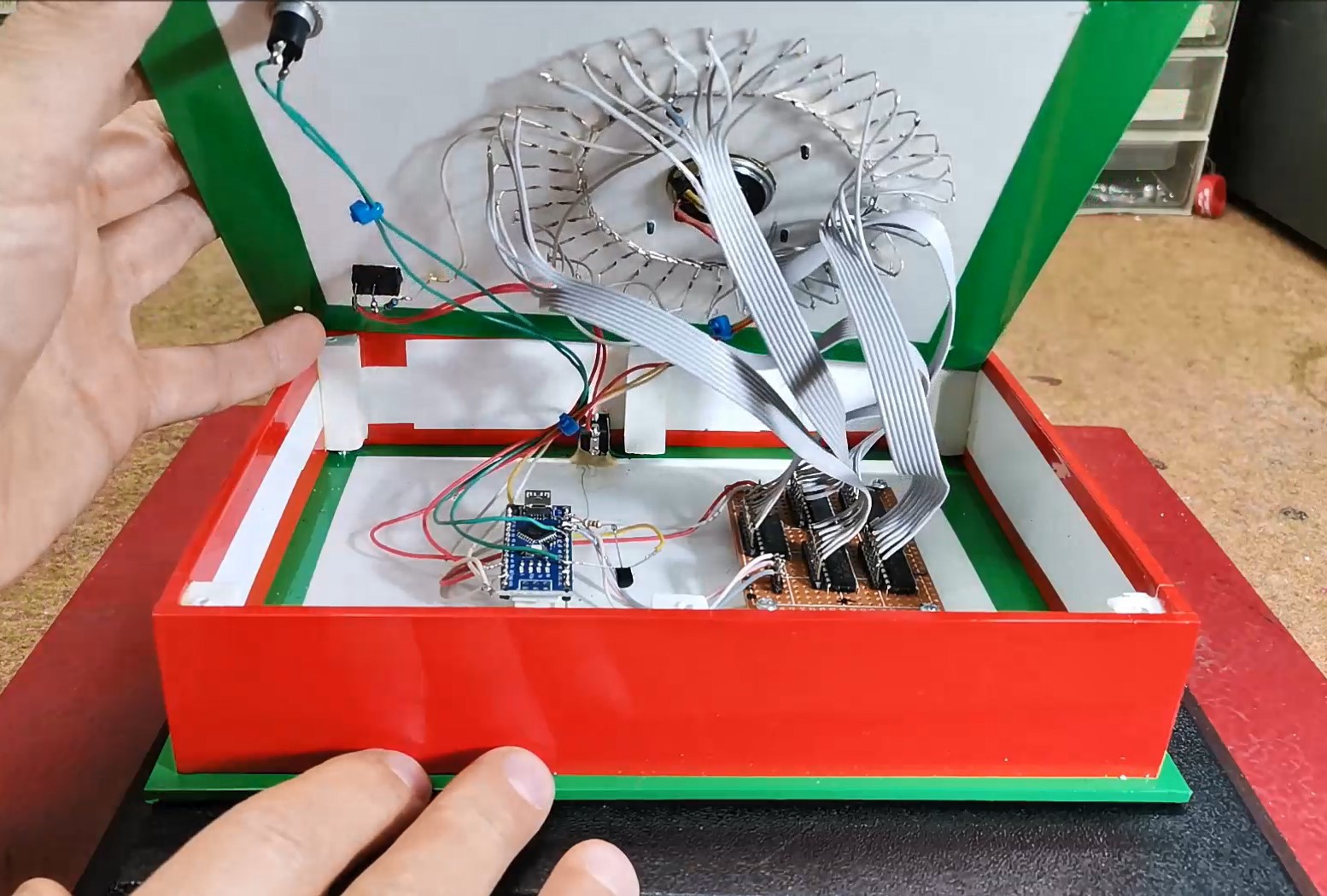
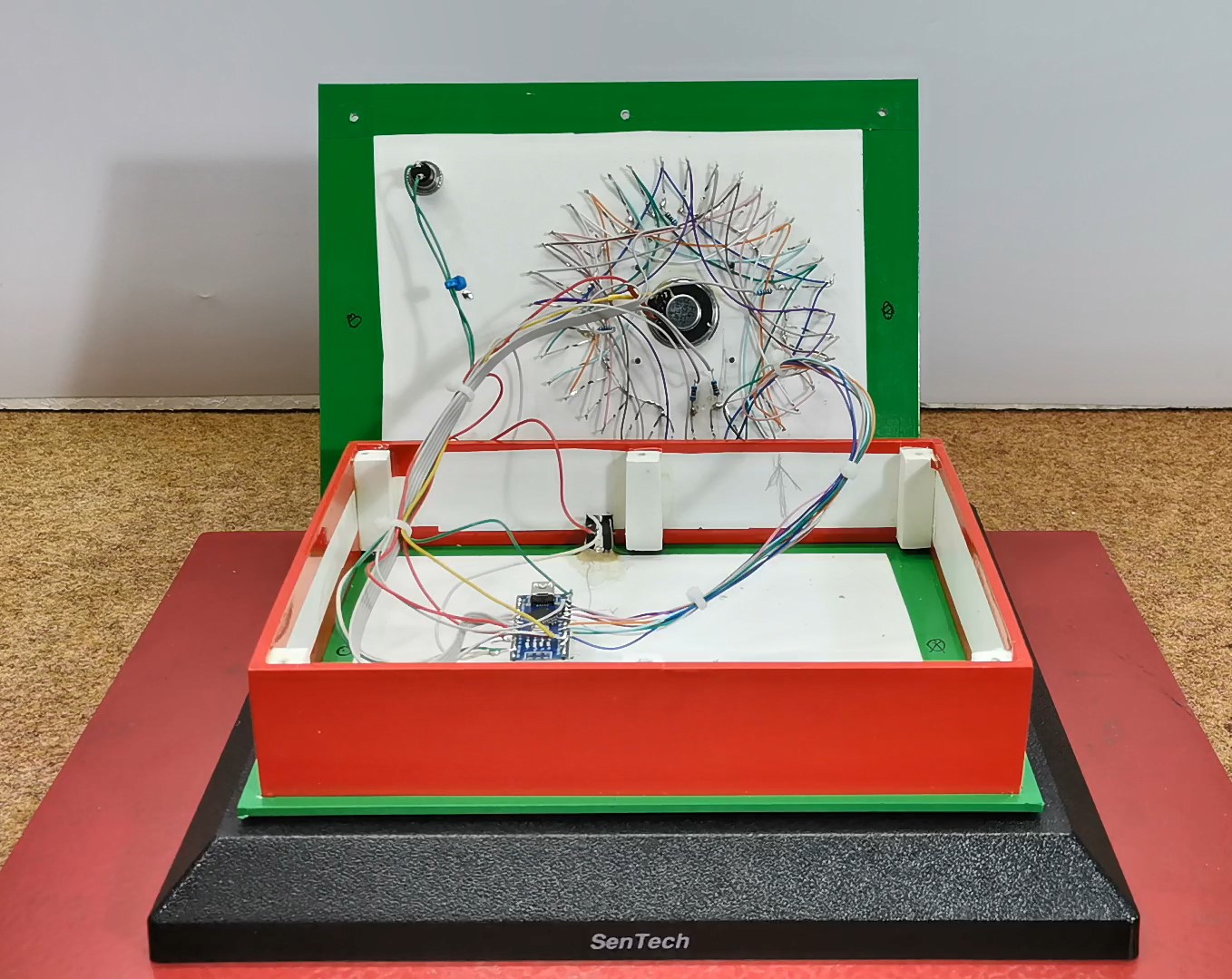
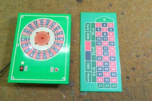
In the following, you can see the way in which the device is made
Finally, the entire device is installed in a suitable box made of PVC board with a thickness of 3 mm and covered with self-adhesive colored wallpaper


This Arduino European Roulette project seems like a fun way to experiment with electronics! If you are into casino-themed projects, you may also be interested in checking out some real-world gaming gambling apps on CasinoDepositPal.com where you will find more detailed information. Visit this site to get an idea of online casino games and strategies. It's amazing how technology can bring the excitement of casinos right into our homes. Happy crafting!