J. M. Hopkins
Development Checklist
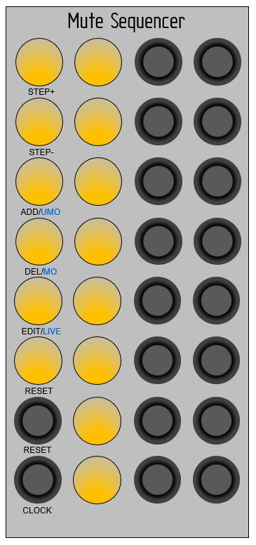
- Define expected behavior and physical layout
- Define physical parts
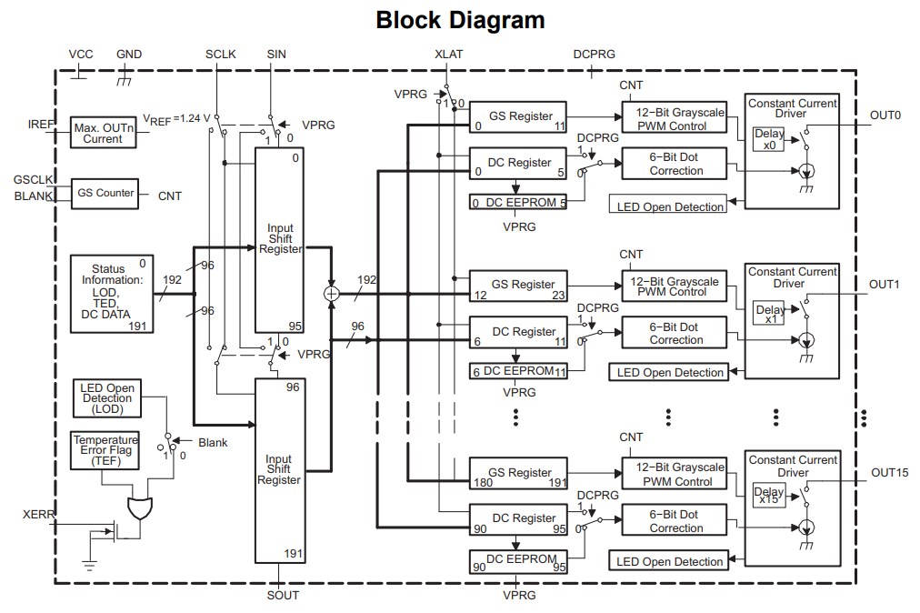
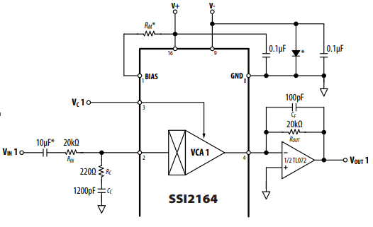
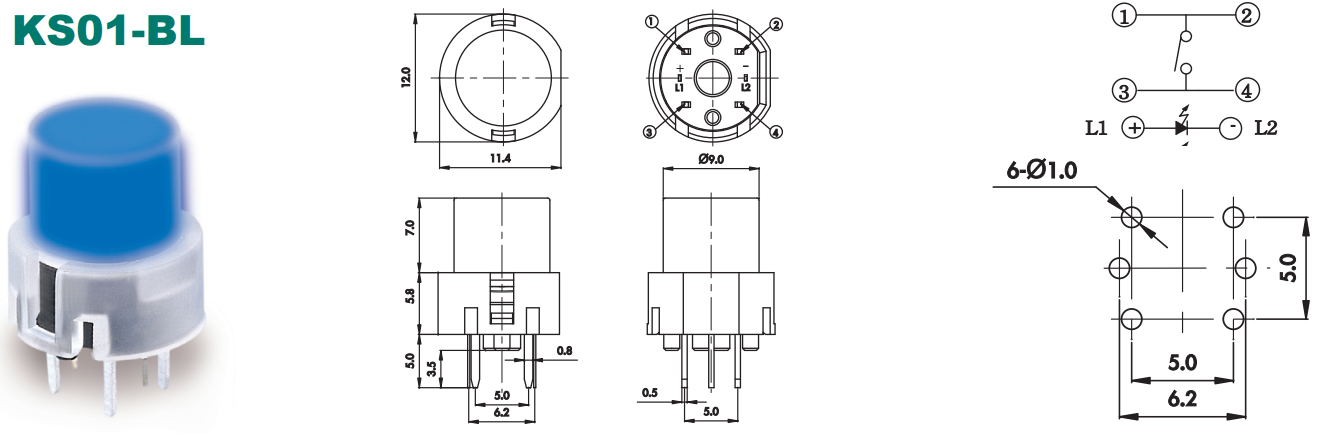
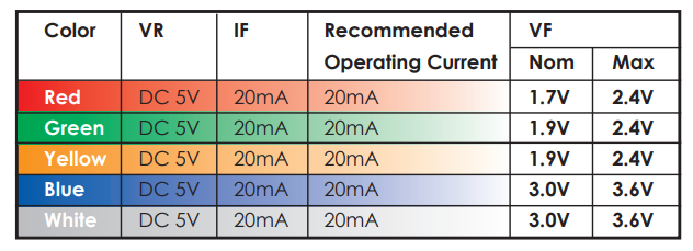
Big LED buttons KS01-BLV-2 20 x ORDERED -> ONHAND/Arrived OpAmp IC TL074 ONHAND VCA IC SSI2164 4 x ORDERED -> ONHAND/Arrived 3.5mm Mono Jacks WQP-WQP518MA-BM 20 x ORDERED -> ONHAND/Arrived Blank Panel 10hp 12hp ONHAND LED IC TLC59401 2 x ORDERED -> ONHAND/Arrived Teensy 4.0 TEENSY40 ONHAND Resistors/Caps * ONHAND - Microcontroller firmware development
- Develop and Breadboard Circuits
- Order PCB
- Assemble PCB
- Test

 Hexabitz
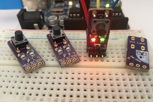
 Owl Labs
 Alain Mauer