Lithium ION
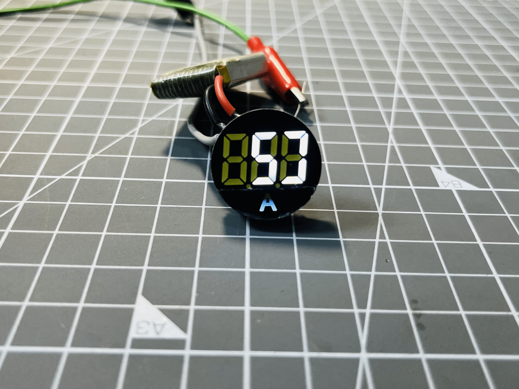
In this tutorial we will know how the digital current meter works and what should be the right approach to design a current meter. Last month I bought this current meter which can measure up to 100A of current. Which I think is very much enough for basic and power electronics purposes.
Usually, we required one transducer or measuring sensor with ADC and microcontroller circuit. A microcontroller can either measure voltage with the Analog to digital convertor or time constant by clock signal. Here as a transducer/sensor Rogowski coil is used and for the display and measuring unit the current sensor has onboard dedicated microcontroller.
Buy from here: Amazon.com (Newer version)
Principle of Rogowski coil:
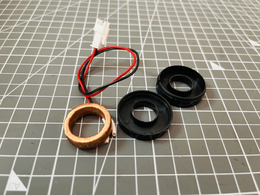
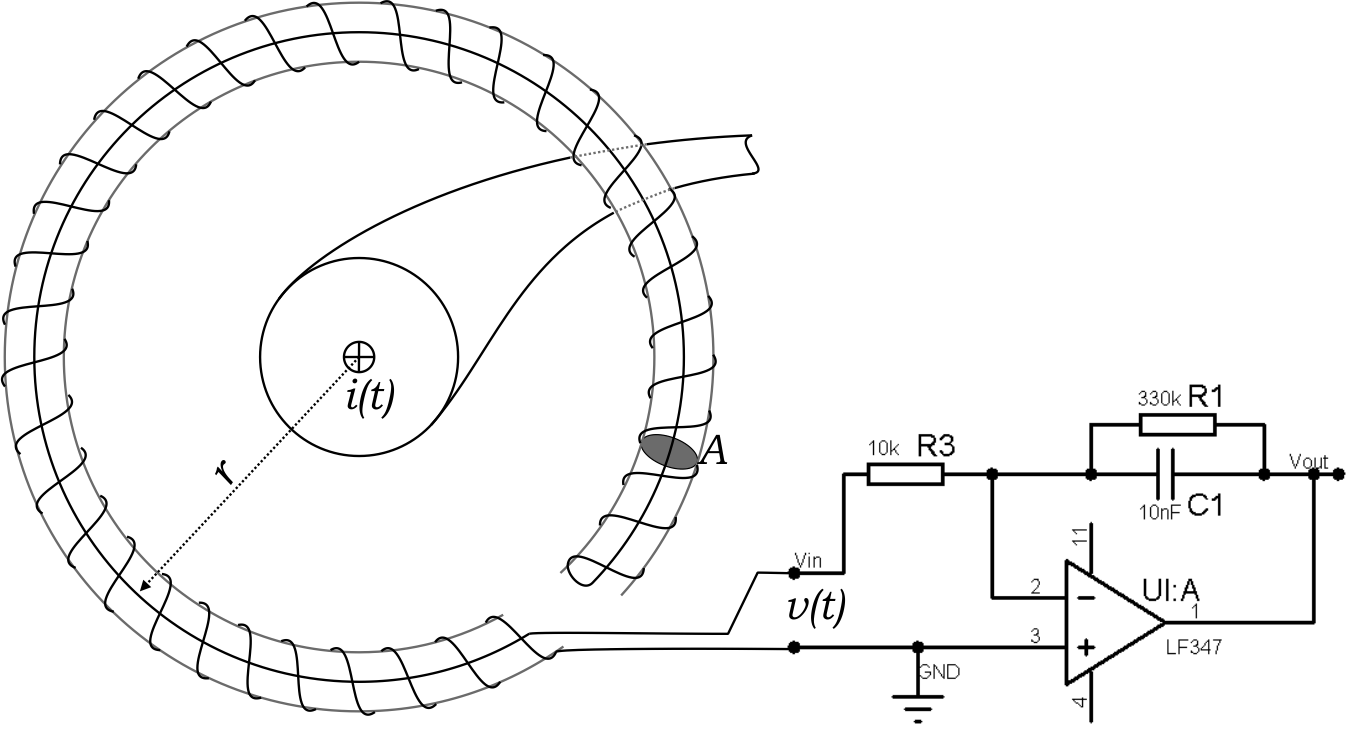
A Rogowski coil is a type of electrical transducer that is used for measuring alternating current (AC) in electrical systems. It consists of a flexible coil of wire that is wrapped around a conductor carrying the AC current to be measured. When the AC current flows through the conductor, it creates a magnetic field that induces an electrical signal in the Rogowski coil.
The electrical signal induced in the coil is proportional to the rate of change of the magnetic field, which in turn is proportional to the current flowing in the conductor. The induced signal is then processed by an amplifier and/or integrator circuit to produce a voltage output that is proportional to the current being measured.
Rogowski coils have several advantages over traditional current transformers. They are non-intrusive, meaning that they do not need to be physically connected to the conductor carrying the current, which makes installation and maintenance easier. They also have a lower saturation point than CTs, which allows them to measure higher currents without saturating or distorting the output signal. Additionally, they are lightweight, flexible and have a high degree of accuracy, making them ideal for a variety of applications.
Power section:
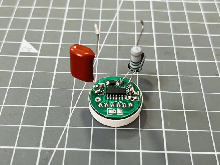
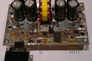
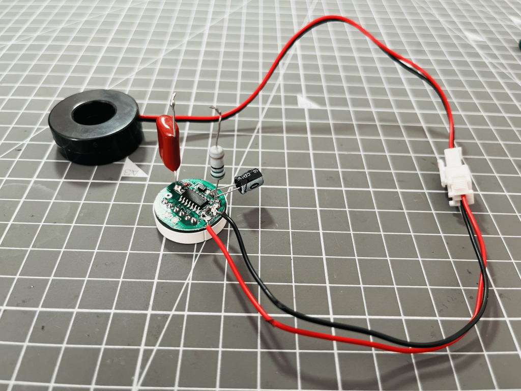
In any measuring device we need a dc operating voltage. The internal circuitry and microcontroller unit of this current meter works on 5volts with a max of 50mA of current. And for this transformer less low power supply is the best solution which includes a high voltage capacitor and a resistor for step down. Then a Zener diode for linear 5volt regulation and a charge storing capacitor.
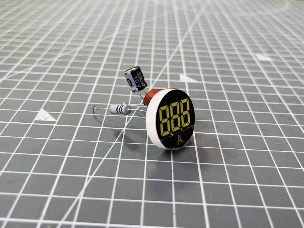
Screen and microcontroller:
On the top of the PCB one single IC is controlling all the circuit which is type of application specific integrated circuit. Which has inbuilt led controller, ADC and computation circuit. The internal ADC has a step size of 0.4milli-volts. The voltage from the Rogowski coil is computed by a voltage division circuit and then fed into the ADC. Here a maximum of 400mv (0.4v) gives the full scale reading of 99.9Amperes.
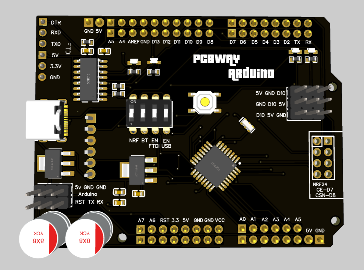
To prototype any type of PCB and for your 3D designs with better material, best service and lower cost, I will prefer to use PCBWAY services. PCBWay has become a trusted name in the industry, delivering a range of services including PCB design, fabrication, assembly, and more. See the previously made Arduino by me using the same PCB service.
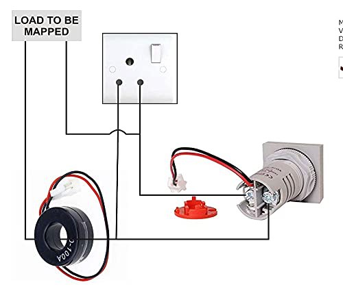
Connection with Ampere meter:
This Current meter works with AC current; both measuring and power circuit need AC (Live and neutral wire). The coil is present for measuring the primary value. Likewise other current measuring units which are based on hall effect only one wire is used to measure the field and the current.
Features:
- Easy for installation
- Compact & small in size
- This is a digital ammeter
- Good environmental Protections
- Very low Power consumption
- Available in various sizes, colors, and voltage rating
Working of the overall circuit:
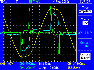
First of all the coil sense the field effects and a generate a corresponding very low voltage due to electromagnetic induction. This voltage then fed to the microcontroller which has inbuilt ADC and all the computation is done there. because any microcontroller can measure voltage not the current that's why the conversion...
Read more »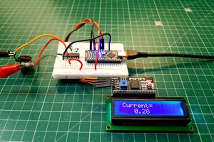
 Sagar 001
 mbsg99