 txyz.info
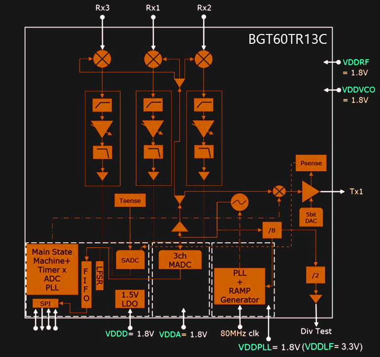
BGT60TR13C is a tiny radar chip, with an 80MHz clock, FSM and FIFO. The radar chip fills the FIFO buffer with ADC raw data. When the buffer is filled, an interrupt is issued. After the interrupt, Amlogic SOC sends a "Burst Mode command", by continuing to send clock shifts out of the FIFO buffer over the MISO.
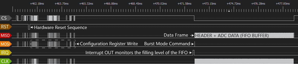
But first, the following Configuration Registers are written by Amlogic SOC:
0000000 1 000111100110100111010000 //0x00 Main register
0000001 1 000010100000101001010000 //0x01 MADC control register
0000100 1 111010010110011111111101 //0x04 PLL analog control register 1
0000101 1 000010000000000001110100 //0x05 PLL analog control register 2
0000110 1 000101000011111000111011 //0x06 SPI and FIFO Control
0000111 1 000000010000111100000000 //0x07 Sensor ADC ctrl reg
0001000 1 000000000000000000000000 //0x08 Channel set idle mode 0
0001001 1 000000000000000000000000 //0x09 Channel set idle mode 1
0001010 1 000000000000000000000000 //0x0A Channel set idle mode 2
0001011 1 000000000000111111100000 //0x0B Channel set control idle mode
0001100 1 000000000000000000000000 //0x0C Channel set deep sleep mode 0
0001101 1 000000000000000000000000 //0x0D Channel set deep sleep mode 1
0001110 1 000000000000000000000000 //0x0E Channel set deep sleep mode 2
0001111 1 000000000000101101100000 //0x0F Channel set control deep sleep mode
0010000 1 000100111111110001010001 //0x10 Channel set 1 (up)
0010001 1 011111111111010000011111 //0x11 CSU1_1 Channel set 1 (up)
0010010 1 000000000001110011100111 //0x12 CSU1_2 Channel set 1 (up)
0010110 1 000000000000010010010000 //0x16 CSC1 Channel set control 1 (up/dn)
0011101 1 000000000000010010000000 //0x1D CSC2 Channel set control 2 (up/dn)
0100100 1 000000000000010010000000 //0x24 CSC3 Channel set control 3 (up/dn)
0101011 1 000000000000010010000000 //0x2B CSC4 Channel set control 4 (up/dn)
0101100 1 000110010011111000001010 //0x2C CCR0 Chirp control register 0
0101101 1 010111000010001000001010 //0x2D CCR1 Chirp control register 1
0101110 1 000000010011000000000000 //0x2E CCR2 Chirp control register 2
0101111 1 101001011011111000011110 //0x2F CCR3 Chirp control register 3
0110000 1 101010000000100010101110 //0x30 PLL1_0 FSU1 – shape 1
0110001 1 000000000000001101011011 //0x31 PLL1_1 RSU1 – shape 1
0110010 1 000000000000010100110010 //0x32 PLL1_2 RTU1 – Shape 1
0110011 1 000000000000000100000000 //0x33 PLL1_3 AP1 – shape 1
0110100 1 000000000000000000000000 //0x34 PLL1_4 FSD1 – shape 1
0110101 1 000000000000000000000000 //0x6B FIFO access
0110110 1 000000000000000000000000 //0x36 PLL1_6 RTD1 – shape 1
0110111 1 000111000110101100010000 //0x37 PLL1_7 SCR – shape 1
0111111 1 000000000000001100000000 //Ox3F PLL2_7 SCR – shape 2
1000111 1 000000000000001100000000 //0x47 PLL3_7 SCR – shape 3
1001111 1 000000000000001100000000 //0x4F PLL4_7 SCR – shape 4
1010101 1 000000000000000000000000 //0x55 RFT0 RF test register 0
1010110 1 000000000000000000000000 //0x56 RFT1 RSVD
0101101 1 010111000001101000001010 //0x2D CCR1 Chirp control register 1
0000000 1 000111100110100111010001 //0x00 MAIN register
From all those registers, I can find only the "0x06 SFCTL - SPI and FIFO Control" register info in the datasheet.
By looking at the SFCTL register 24bit value I can see that:
- PREFIX_EN = 1, which means BGT60TR13C is going to write also HEADER into FIFO
- FIFO_CREF = 7739, when filling level is > FIFO_CREF an interrupt is issued
After configuration is done, Amlogic SOC sends the Burst Mode command in the loop.
There are 30 burst commands per second. The Burst command is well described in the BGT60TR13C datasheet.
Each Busrt Mode command generates a Data Frame (180Kbit length), a Data Frame composed of 24-bit data blocks.
BGT60TR13C Data blocks organization in the Data Frame
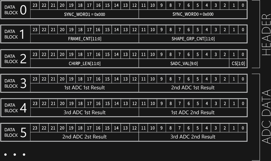
Following DATA BLOCKS are decoded from FIFO_read_loop.dsl recordings:
[#0] 000000000000         000000000000
[#1] 010111101011=1515    000000000000
[#2] 000100000000=256     1011110001=753 00
[#3] 100011101110=2286    101001001010=2634
[#4] 100000100100=2084    100100111010=2362
[#5] 101110011011=2971    100000010011=2067
...

[#0] 000000000000         000000000000
[#1] 010111101100=1516    000000000000
[#2] 000100000000=256     1011110000=752 00
[#3] 100011101100=2284    101000001100=2572
[#4] 100000101100=2092    100100110000=2352
[#5] 101101101100=2924    100000011000=8290
...
Discussions
Become a Hackaday.io Member
Create an account to leave a comment. Already have an account? Log In.