ElectronicABC
GERBE PCB
https://mega.nz/file/jURkCTyJ#6GlqXlrVa8WI1L1c6J4CiD7IGIgRqF4kAn6hfb3iu3Y
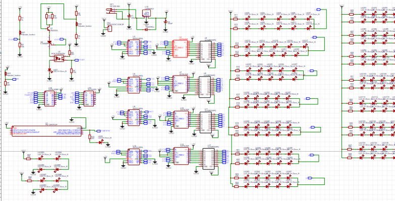
SCHEMATIC DIAGRAM
Here we will see the schematic diagram and all the electronic components that we have used for this project and we will also add the pdf of the schematic diagram so that you can visualize it better
https://mega.nz/file/bIBQUKBS#Tnv2Kl7VkL26CXylV32wgq4iwBFKvP0zsXUgYAzvd1k
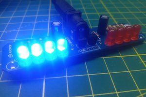
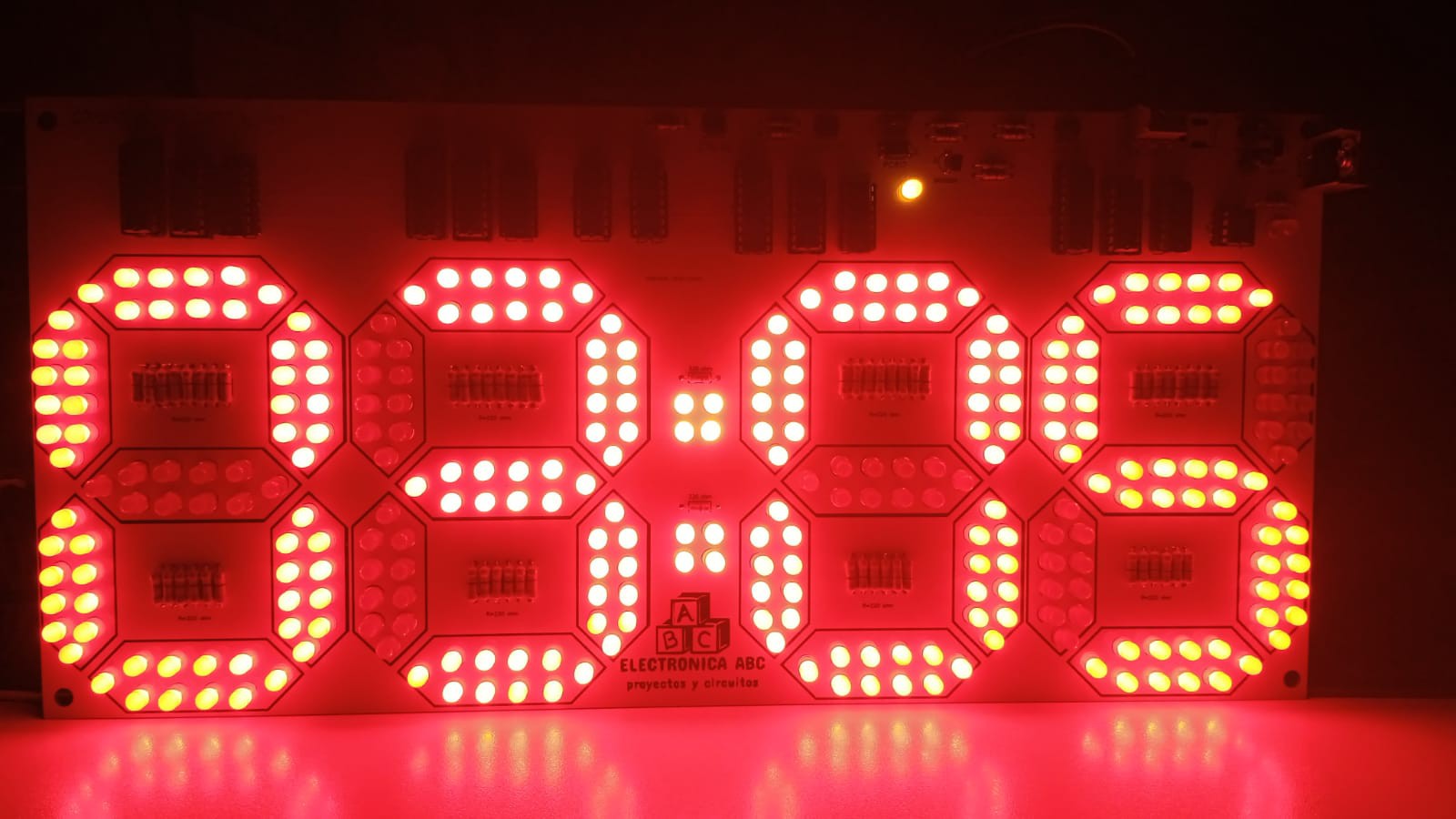
FUNCTIONING
OPERATION IS VERY EASY FIRST WE WILL FEED 12VDC SO THAT OUR CIRCUIT WORKS INTERNALLY IT HAS A 5VDC REGULATOR FOR THE CONTROL STAGE OF OUR COUNTERS AND 12VDC FOR THE ASSOCIATION OF OUR LEDS IN SERIES AND THE ULN2803
SUBSEQUENTLY, OUR CIRCUIT HAS 3 PUSHBUTTONS THAT WILL ALLOW ME TO GIVE START, STOP AND RESET OUR TIMER HAS A MAXIMUM COUNT OF 99 MINUTES
AND IT HAS A START LOCKING SYSTEM TO START THE COUNT AND TBM A STOP TO STOP THE COUNT WHERE YOU WANT AND THEN FOLLOW AGAIN IF I WANT OR RESTART IN ANY CASE
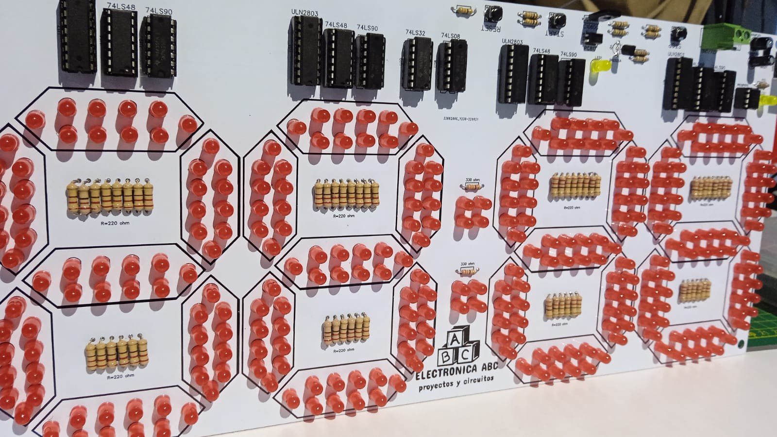
OUR PROJECT USES 74LS90 COUNTERS UP DECIMAL COUNTERS AND TO BE ABLE TO GOVERN MANY LEDS WE ARE USING THE ULN2803
TO HIGHLIGHT THAT OUR CIRCUIT USES AN NE555 AN ASTABLE MULTIVIBRATOR FOR THE CLOCK PULSE
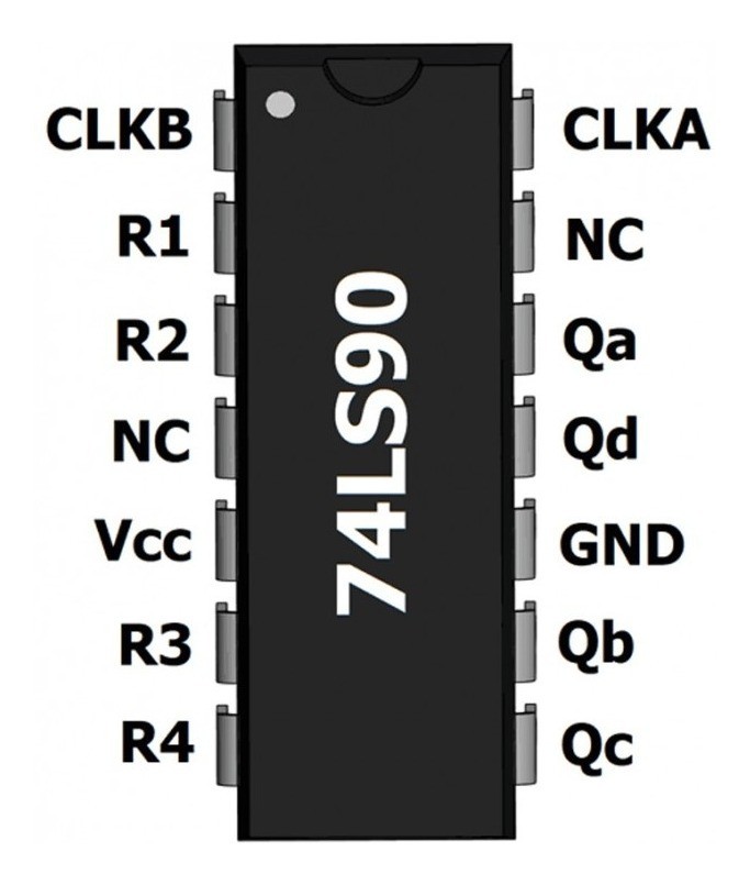
74LS90
74LS90 Counter Description
It is a counter that has the exclusive function of cyclically counting the quantities from 0 to 09 with respect to the flow of the circuit in general.
In addition, it is made up of four fixed elements in which a constant contact is developed where the flow of information forms a kind of flip-flops, that is, a natural clash between them.
The integrated 74ls90 has two types of counts that are the following:
Up counting (count up): The LOAD input must be at high level, the ENABLE input at 0 for the count to be enabled, and also the DU (Down/Up) input must be at low level.
Down count (count down): The LOAD input must be at high level, the ENABLE input at 0 for the count to be enabled, and also the DU (Down/Up) input must be at high level.
main features
Support TTL input
CMOS output
Applications: Industrial
ULN2803
What is ULN2803?
The ULN2803 is a chip, an integrated circuit with traditional DIP packaging, like so many others. That is, with two stacks of pins on its sides. Well, so far it may seem like so many others, but inside it does not have conventional logic gates, multiplexers, filters, current sensor modules, shift register, nor a microcontroller either...
Inside the ULN2803 you will find drivers, with a series of transistors, some devices that I have already talked about on other occasions with different types such as: MOSFET, BC547, 2N3055, 2N222, etc.
The Darlington transistor is not a transistor as such, but a pair of them connected in a very specific way. Two connected bipolar transistors will form the Darlington pair, which allows the current amplified by the first transistor to enter the base of the second transistor and be amplified again.
This type of amplification was used with two separate transistors, but a Bell Labs engineer named Sidney Darlington patented the combination in 1952. The idea was to put two or three transistors on a single monolithic chip. An idea similar to that of creating a chip or integrated circuit, although this achievement is not recognized for him, as you well know...
The Darlington pair behaves like a single conventional transistor, that is, after the combination of the two transistors it still has a single base, a collector and an emitter. Only that the current gain will be the combined one, and therefore greater than using only one transistor. Specifically, it is considered that the Darlington gain is approximately the result of the product between the two gains of the transistors used separately.
The advantages of using this Darlington pair is clear, obtaining a large current gain. This makes it possible to control currents of a higher magnitude with a small base current. But it also has its drawbacks, such as a larger phase shift at high frequencies than when using a single transistor, which makes using them in circuits...
Read more »
 jaromir.sukuba
 Tim
Tim