 Rupert Hirst
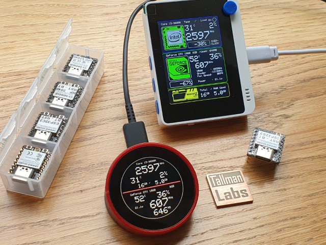
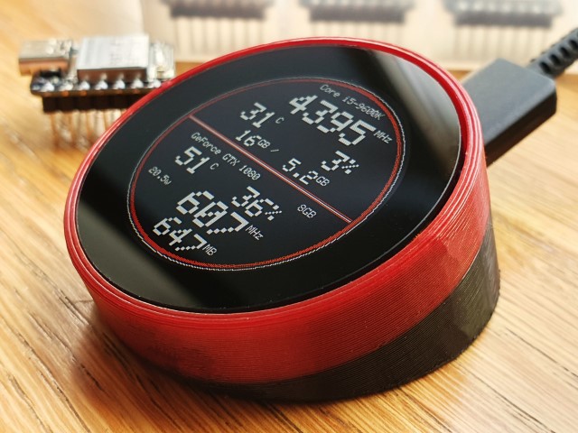
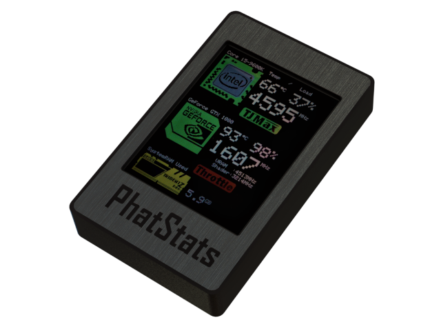
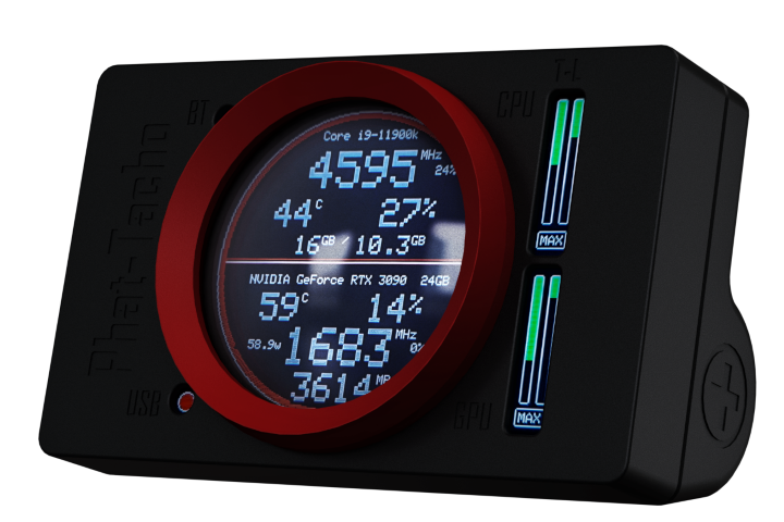
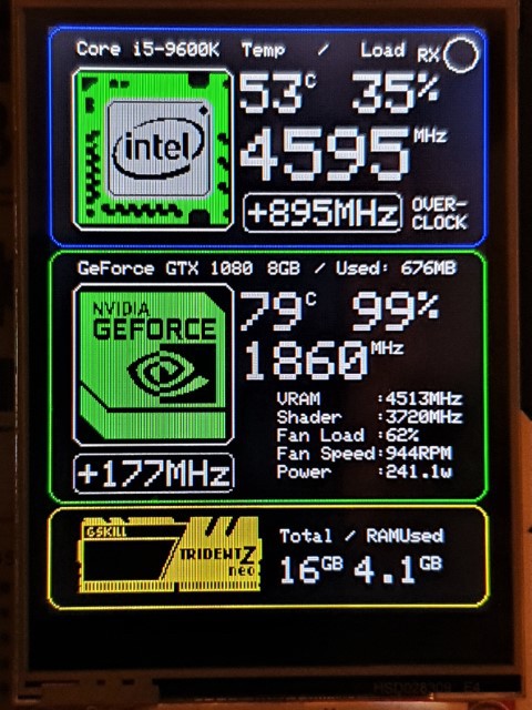
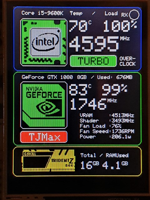
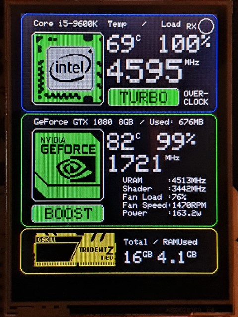
PhatStats (TFT) form an Arduino serial display. HardwareSerialMonitor is a PC serial client, both are written by Rupert Hirst and Colin Conway.
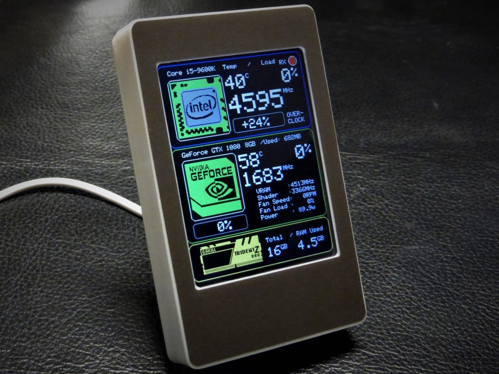
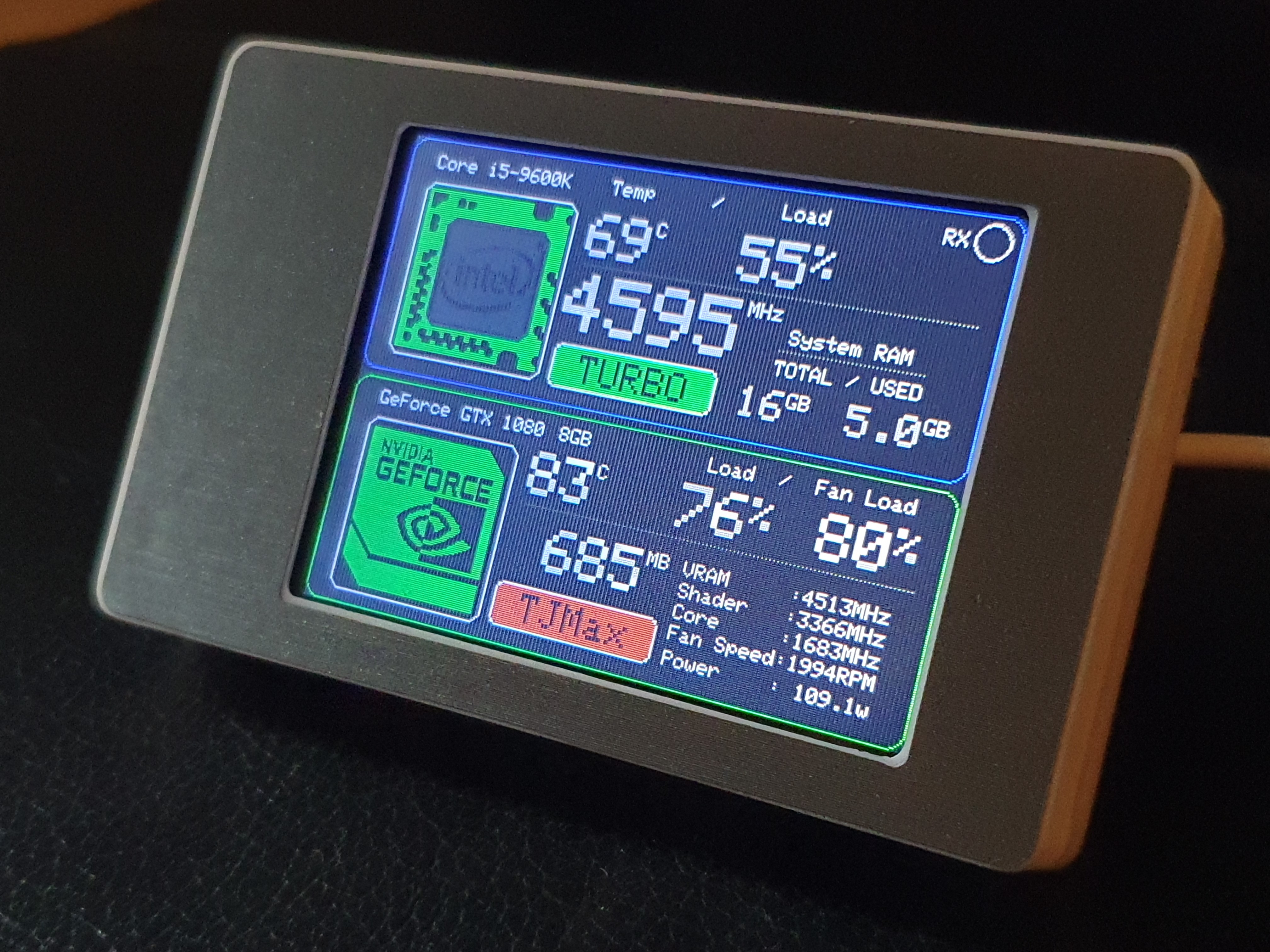
HardwareSerialMonitor Windows client reads the hardware statistics from the PC.
This data is forwarded over the hosts’ serial port to an Arduino compatible micro processor. It is then, displayed using the Phat-Stats sketch.
This project, assumes you have a above average experience with Arduino, the IDE and the compatible boards available.
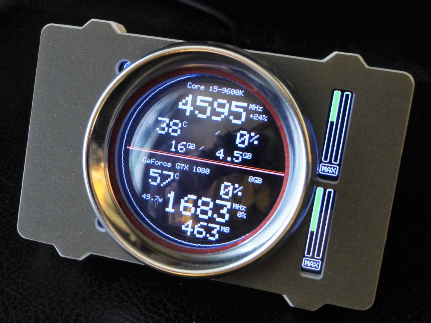
The HardwareSerialMonitor was designed for dedicated GPU's . Your mileage may vary with Integrated Graphics
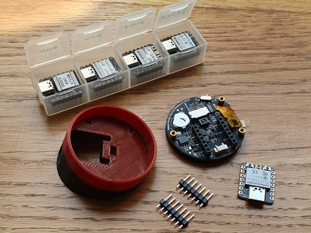
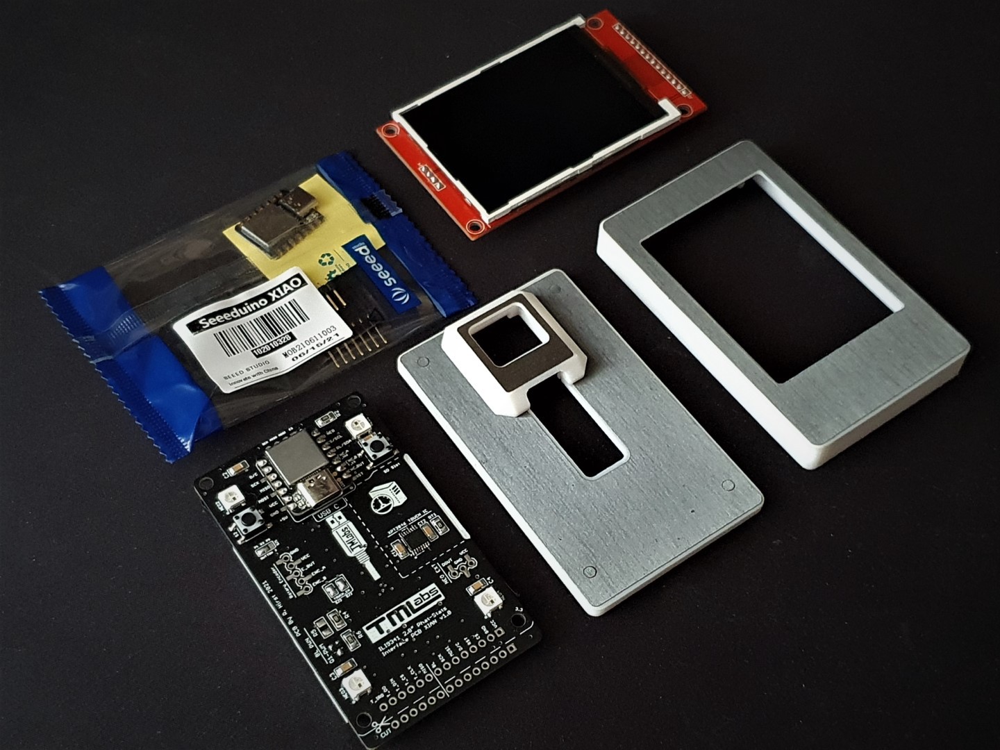
To help with construction there are hook up guides, links below:
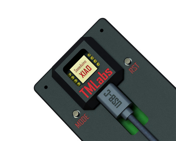
Phat-Stats ILI9341 TFT Display Hook up Guide
Going Forward:
The project needs to be ported over to LibreHardwareMonitor , a fork of OpenHardwareMonitor for future support, as this gets a lot more updates for new PC hardware. If anyone can help please get in touch, thanks.
http://runawaybrainz.blogspot.com/
https://github.com/koogar/HardwareSerialMonitor
https://github.com/koogar/Gnat-Stats
Gnat-Stats (OLED) has moved to a new project page here
The above software/code is licensed under the following terms:
--------------------------------------------------------------------------------------------
GPL v3
Gnat-Stats, Phat-Stats & Hardware Serial Monitor Copyright (C) 2016 Colin Conway, Rupert Hirst and contributors
This program is free software; you can redistribute it and/or modify it under the terms of the GNU General Public License as published by the Free Software Foundation; either version 2 of the License, or (at your option) any later version.
This program is distributed in the hope that it will be useful, but WITHOUT ANY WARRANTY; without even the implied warranty of MERCHANTABILITY or FITNESS FOR A PARTICULAR PURPOSE. See the GNU General Public License for more details.
You should have received a copy of the GNU General Public License along with this program; If not, see http://www.gnu.org/licenses/.
HardwareSerialMonitor only was inspired by Psyrax's "SerialSender". Psyrax is given attribution and thanks, by being an honorary member of the project.


 mircemk
 myPinballs
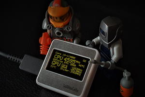
Sorry there was no replay bottom so I send new one here
you asked "Whats the screen brightness like when you connect it straight to 3.3v?"
It's great when connected straight to 3.3v but when I connect it to the pin 4 it's very dim
No I don't use any resistor