 ElectroBoy
Operational amplifiers are awesome, they are used to design a lot of circuits. And has a wide application in electronics. In previous part we have discussed the open loop gain/ comparator feature of an operation amplifier. And now we will see the use of operational amplifier to amplify a very small signal with adjustable gain. In end we will make a DC amplifier which can be tuned easily through the onboard potentiometers. All the circuitry embedded on a small piece of PCB, by the way you can use Custom PCB service from here.
Op amp configurations and gain settings:
There are two types of configurations (Inverting and non-inverting) while using the operational amplifier in closed loop. In an operational amplifier the loop is said to be closed, if one end of the output is connected to the input through any resistor network.
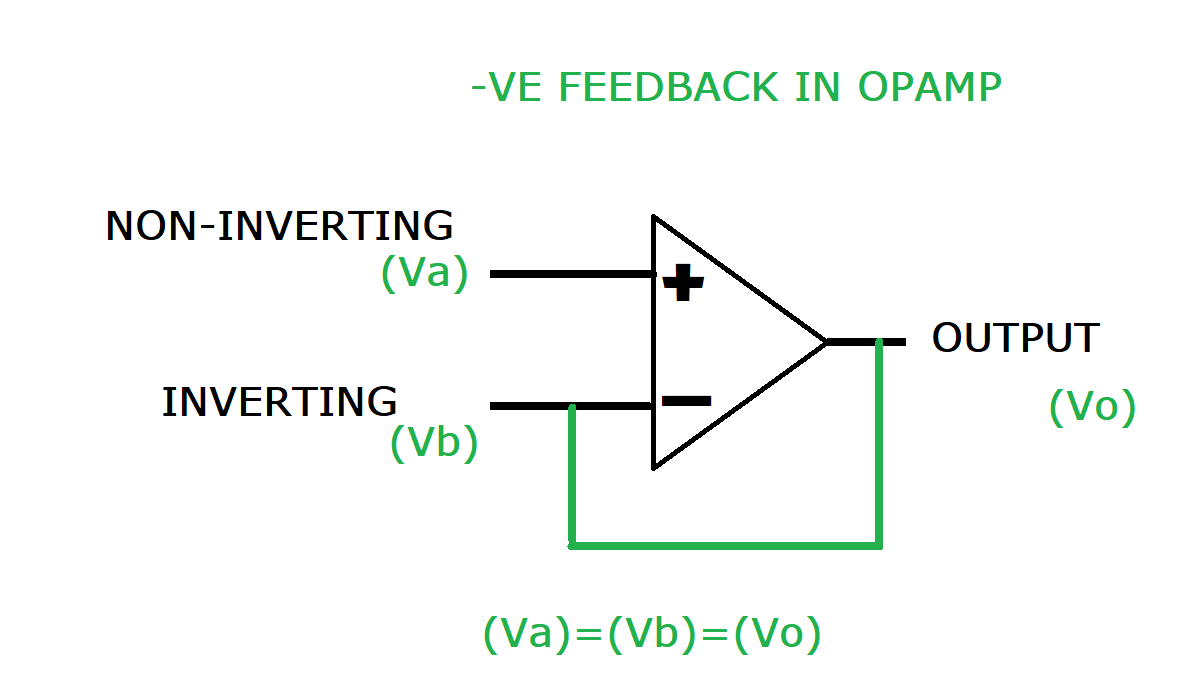
Both the configurations use negative feedback because it helps to minimize the error/ noise and increase the overall stability in the system. Feedback is always given on inverting pin in both configurations which is defined as negative feedback.
The concept of virtual ground:
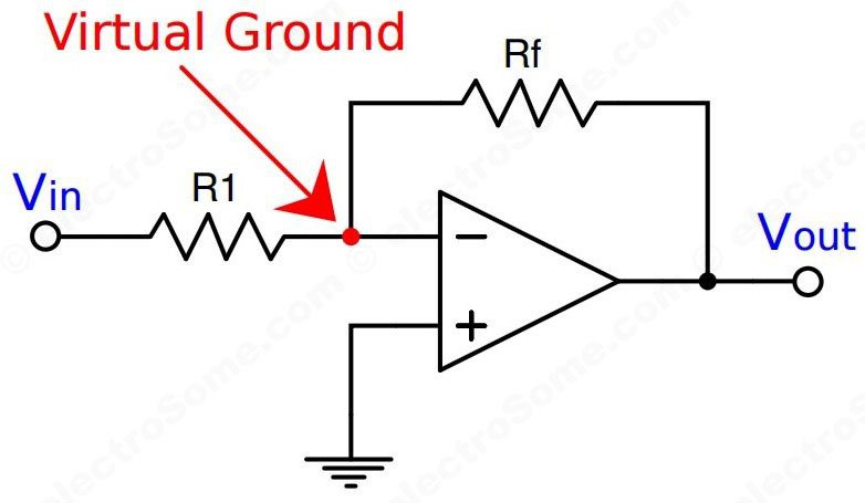
In the closed loop configuration of the operational amplifier. The virtual ground concept is there in which operational amplifier tries to minimize the error of the applied input signal. Example: if the inverting terminal is held at ground potential, then the non-inverting terminal also assumed at ground and all the observations made according to it.
Operation amplifier in non-inverting configuration:
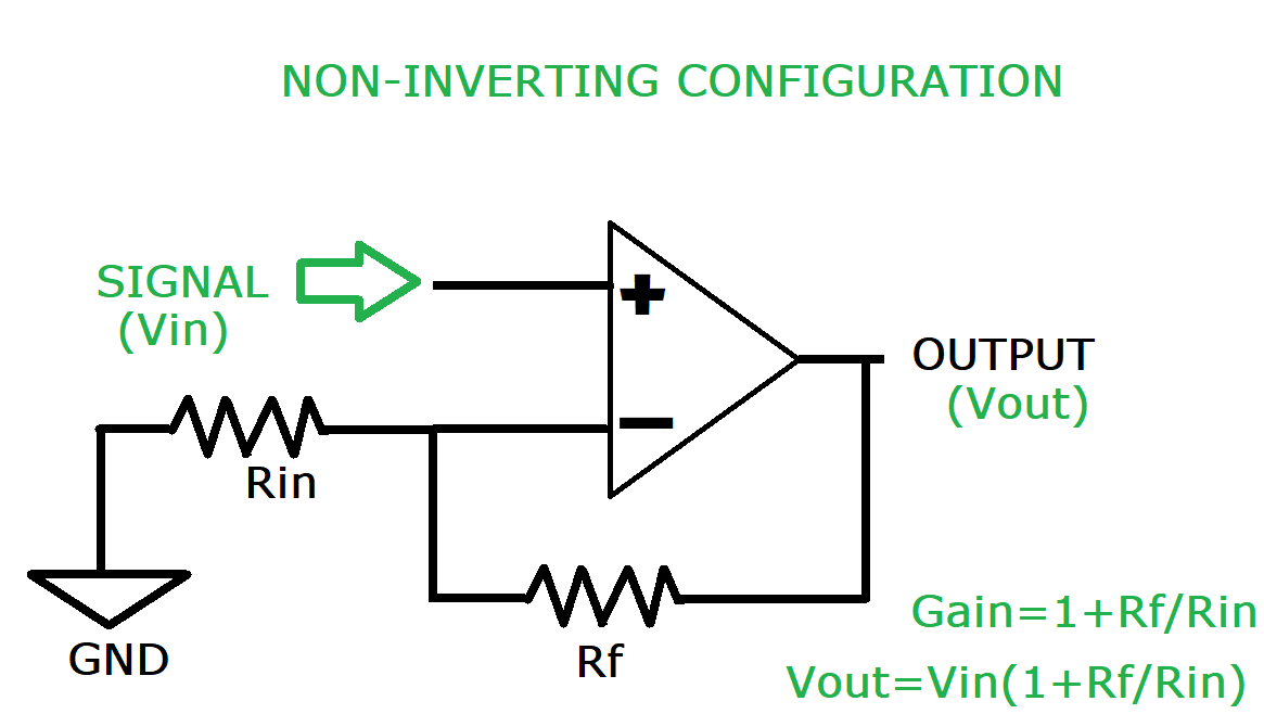
The signal input is given on the non-inverting terminal. On the inverting pin a resistor network of Rf (feedback resistor) and Rin (Input resistor) completes the circuit. While applying KCL on this circuit it is assuming that no current flowing through the terminals of OP-AMP and the input impedance of assumed to be infinity. Which set the overall gain of this configuration and given by 1+Rf/Rin.
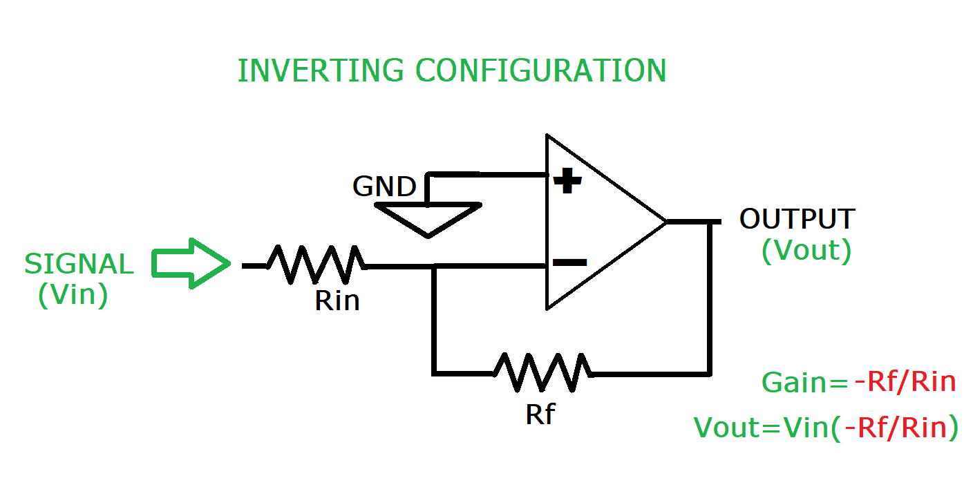
Inverting configuration:
In this configuration the signal is applied on the inverting input after the resistor network. That is why the configuration is named as inverting one. And the non-inverting simply grounded(for reference). Because we are applying signal on inverting pin the output is 180 degrees out of phase to the input. Here the overall gain is given by -Rf/Rin.
Using these configuration we can design different amplifier circuits including DC amp, AC amp and differential amp, audio preamps. See the below given example and read the 3rd step it is most important.
A basic DC amplifier working concept:
Let’s take an example where we have a signal of 10mA and we want to amplify the signal to 1 volt, so a gain factor of 100 is required.
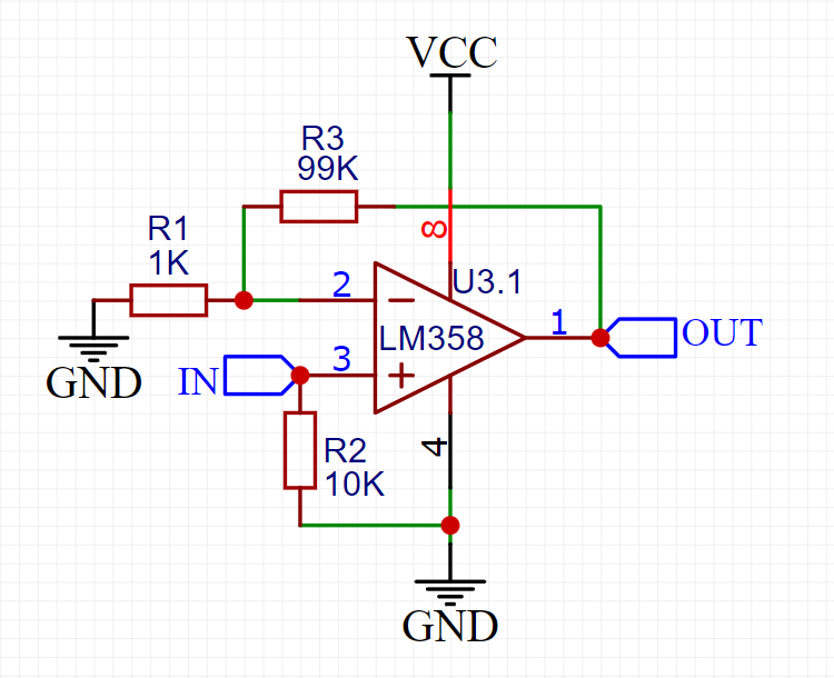
Step 1: Choose the configuration, it is easy to work with both configurations but here I am choosing non-inverting configuration which gives a gain factor of 1+Rf/Rin.
Step 2: Choose the value of Rf and Rin according to the Gain.
Gain= 100
100= 1+RF/RIN (Assume Rin be 1k and calculate for Rf)
we required the RF= 99K, Rin=1k for the gain of 100
Step 3: Because in closed loop the operational amplifier tries to minimize the difference between both the input terminals. We need to give a reference from the non-inverting terminal to ground. This set a reference line and the gain is amplified by the same factor as of applied input signal. The AC amplifier holds a different approach which will be discussed in next tutorial of the series “Operational amplifiers are awesome”.
Adjustable operational Amplifier DC amplifier:
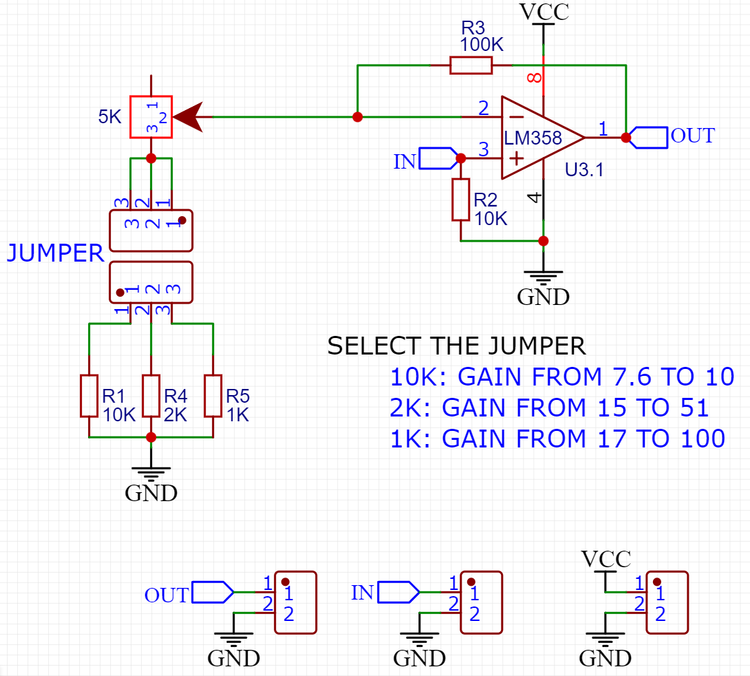
I made this DC gain amplifier which can be adjusted according to the input applied and here you will find 3 different modes which sets the gain 10x, 50x and 100x so it is easy to amplify and test any dc signal out from any device. Gain can be selected by switching the jumper to different position on PCB.
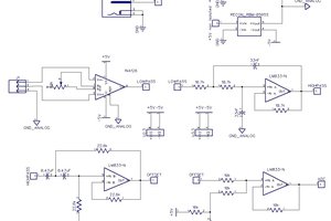
Gerber files and circuit diagram:
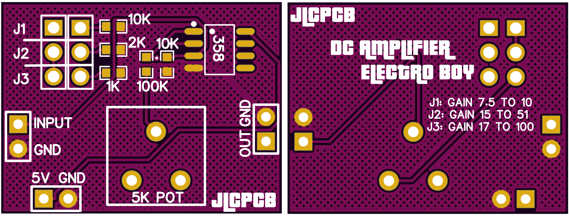
You can download all the circuit details and Gerber files from here to order directly. They provide...
Read more »
 Ghani Lawal
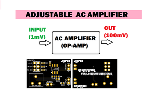
 Jesse
Jesse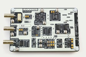
 Mark Omo