 zpekic
The main point of this project was to recreate a working CPU by following a technical document from 1978, illustrate micro-programming in a practical way and recreate the ICs (especially Am29XX) from the era in a FPGA.
Maybe not the best (which would be to run dedicated test programs) but the most fun way to verify if the CPU works is to create a small working system around it, running Basic.
The small system is similar to SBCs (single board computers) available for many 8-bit CPUs, closest is probably 8085 MiniMax.
Project top level source file (sys9080.vhd) describes the SBC mostly through structural VHDL design approach, and can be roughly represented as:
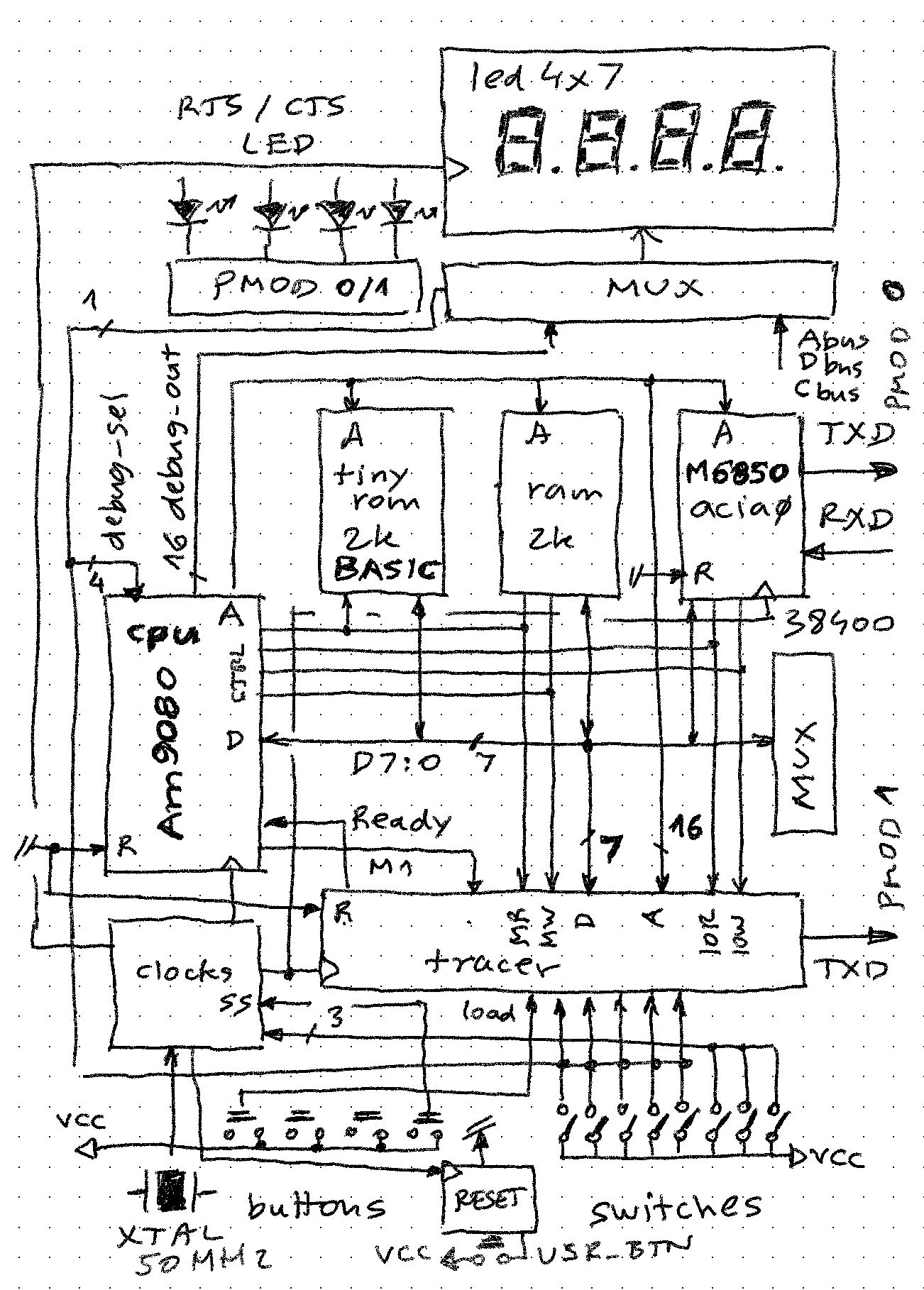
(note a bug in the sketch: MUX in center right has arrow in wrong direction, it can only drive DBUS, and takes input from either switches or buttons - so CPU can read these as port 00H and 01H)
Key components (as they are named in top-level source file):
cpu
Details are described here. While Intel 8080 compatible, there are some differences:
- Bus control signals are directly available, as if Intel 8228 was in the system too
- Like everything else inside the FPGA, it is static, with clock frequency working from 0 to 25MHz (not tested above that)
- There is a debug port that allows any register pair to be read, or microinstruction program counter / instruction register be read. However it is commented out to save FPGA real estate.
- DMA and Interrupts are not used / hooked up (but tested and they work - only RST x instructions for interrupt response)
ram (2k*8)
Source code is here. Very similar to the static RAM ICs of the era, such as 6116. It is implemented using Xilinx-specific component to be able to fit into the design (ISE 14.7 was not able to map/pack the generic VHDL defined design into the modest Spartan XC3S200A FPGA as the design was getting too big. It repeats 31 time in the memory address space (everywhere outside ROM taken space, so 0800H - FFFFH)
tinyrom (2k*8)
Similar to EPROMs of the era, such as 2716. It contains Tiny Basic, or can contain any other 2k system program (e.g. a monitor) in the 0000H-07FFH address space (8080 family of CPUs require readable and defined RST n target addressed in range 0000H-0038H. Its size and contents is defined in parametric way:
-- ROM 2k at 0000H to 07FFH
-- See http://cpuville.com/Code/tiny_basic_instructions.pdf
    tinyrom: entity work.rom1k generic map(
        address_size => 11,
        filename => "..\prog\zout\tinybasic2dms.hex",
        default_value => X"76" -- HLT
    )
    port map(
        D => data_bus,
        A => address_bus(10 downto 0),
        nOE => nTinyRomEnable
    );
This project log provides details how a file name parameter leads to build-time initialization of ROM memory using hex file format.
acia0
This device mimics the popular MC6850 ACIA of the era. Mimics because it only supports features in its control and status registers that are used by Tiny Basic. For example, no interrupts for example or modem control pins are supported. It is an aggregation of:
- Serial to parallel converter - this works on the delay line principle (not a state machine!) and is driven by 4*RXD clock rate. It is able to detect any parity and 1-2 stop bits, but the data bit count is always 8.
- Parallel to serial converter - works as a counter driven MUX, not as a shift register. It is able to generate any parity and 1-2 stop bits, but data frame is always 8 bits.
- Glue logic that implements 8-bit data, status and control registers, with key bits compatible to MC6850 - such as:
- TDRE (transmit data register empty) - code is waiting for this bit to go high before sending out a character
- RDRF (receiver data register full) - code is inspecting this bit in a loop to check if a new character has arrived
D <= d_out when (int_read = '1') else "ZZZZZZZZ";
d_out <= rdr when (RS = '1') else status;

status(7) <= '0';        -- no interrupt
status(6) <= err_parity;    -- parity error
status(5) <= err_overrun;    -- receiver overrun
status(4) <= err_frame;        -- framing error
status(3) <= '0';        -- clear to send
status(2) <= '0';        -- data carrier detected
status(1) <= tdre;    -- transmit register empty
status(0) <= rdrf;    -- receive data register full
tracer
Maybe the most interesting component in the design, because it is simple yet it allows observing any bus cycle remotely, and for instruction fetches tracing them in assembly source code format. It silently listens to bus signal activity (levels of IORD, IOWR, M1, MEMRD, MEMWR signals) and if right pattern is detected, stops the cycle using READY signal until the record describing the cycle is output on serial UART pin.
clocks
The system uses a variety of clock signals, and their generation is centralized in this component. The source is 50MHz main FPGA clock signal, from which others are derived using frequency dividers. Main outputs are:
- TX and RX clocks for ACIA. These are 38400 and 153600 Hz, for the 38400 send/receive baud rate
- CPU clock
-- connect to outputs
with cpuclk_sel select cpu_clk <=
    ss when "000",    -- single step
    freq_2048(9)    when "001",    -- 4Hz
    freq_2048(7)    when "010",    -- 16Hz
    freq_2048(5)    when "011",    -- 64Hz
    freq_25M(4)    when "100",    -- 1.5625MHz
    freq_25M(3)    when "101",    -- 3.125MHz
    freq_25M(2)    when "110",    -- 6.25MHz
    freq_25M(0)    when others;    -- 25.0MHz
"cpuclk_sel" is a 3-bit value that comes from Mercury baseboard switches 0-2, allowing these CPU speeds to be selected. When set to 000, pressing baseboard button 0 allows stepping machine cycle by machine cycle.
led4x7
This is a standard 7-segment LED driver. It takes 16 bits (4 hex digits) and visualizes them onto 4 7-seg LEDs on Mercury baseboard. It has some "fancy" features such as individual blanking of digits, blanking of whole display (this is used for flashing effect when READY is low, meaning tracer component is active), and driving the 4 dots individually.
The 16-bit input is output of a 20-bit wide "led_bus". Upper 4 bits are supposed to connect to 4 LEDs on the Mercury board (but currently are driven from PMOD pins). The led_bus can display either a subset of bus signals (A7:0, D7:0, control), or debug output from CPU.
Other components include:
- Reset circuit which ensures at least 4 clock period long reset signal when button on Mercury board is pressed
- "inport" MUX which allows reading 8 switches and 4 buttons as I/O ports 00H and 01H respectively
- "on_rts1_pulse" - simple flip-flop that allows starting/stopping the tracer by pressing the space bar on the host (if running the tracer.exe utility)
-- Tracer works best when the output is intercepted on the host and resolved using symbolic .lst file
-- In addition, host is able to flip RTS pin to start/stop tracing
-- See https://github.com/zpekic/sys9080/blob/master/Tracer/Tracer/Program.cs
rts1_pulse <= PMOD_RTS1 xor rts1_delay;
on_rts1_pulse: process(reset, rts1_pulse)
begin
    if ((reset or btn_clk) = '1') then
        continue <= '1';
    else
        if (rising_edge(rts1_pulse)) then
            continue <= not continue;
        end if;
    end if;
end process;
            ConsoleKeyInfo key;
            bool exit = false;

            while (!exit)
            {
                key = Console.ReadKey();
                switch (key.KeyChar)
                {
                    // TODO: clear instruction counter on some key
                    case ' ':
                        comPort.RtsEnable = !comPort.RtsEnable;
                        break;
                    case 'x':
                    case 'X':
                        // leave it in enabled state
                        exit = true;
                        comPort.RtsEnable = true;
                        GenerateProfilerReport();
                        break;
                    default:
                        break;
                }
            }
            comPort.Close();
Discussions
Become a Hackaday.io Member
Create an account to leave a comment. Already have an account? Log In.