 thpoll
An exciting moment as I worked really long time to get to that point.
My designed keyboard PCB and aluminium plate arrived! As usual for JLCPCB you get a minimum of 5 pieces. If you chose to assemble, you have to assemble at least 2! However, that is fine for me, as it gives my the chance to connect two boards of the split keyboard and prototype a bit further. Sure, two left sides, but it doesn't matter for testing the software communication.
First, I tested if plate and PCB fits together:
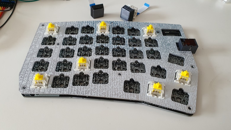
I really like how the silk screen turned out and the alignment of PCB and plate is great. Unfortunately, the key switches sit a bit lose as I needed another notch at the top of every switch to let the LED shine through (the actual LED slit will be occupied by the flex cable of the OLED displays). So, next time, I will try to make them a bit tighter.
Testing the power supply next:
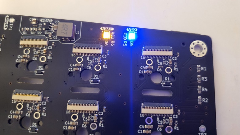
Glad that those work and also give the right voltages. I was a bit worried about that as I don't have much experience here. In the end I just followed the data sheet of the ICs and hoped it works out (on my previous macro pad I used boost/buck converters from AliExpress but wasn't too happy with them).
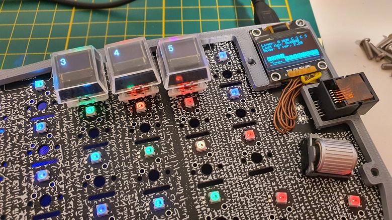
As JLCPCB does only one side PCBA, I had manually solder on the front side LEDs and one of the shift registers, which I decided to put under the keyboard status display. In the end not the best decision since the space under the display is much more limited than expected and I had to move SMT parts on the backside of the display:
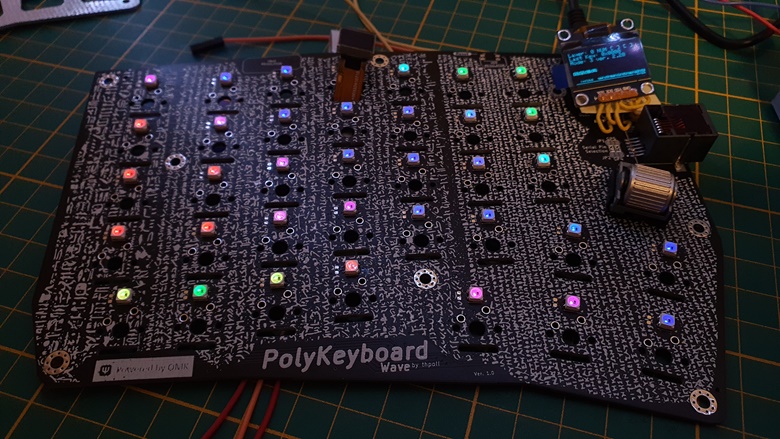
Luckily, that all worked out and a first test shows all LEDs and the status display come to live. This was still without the RP Pico directly soldered to the backside.
Before doing that, I had to apply some fixes:
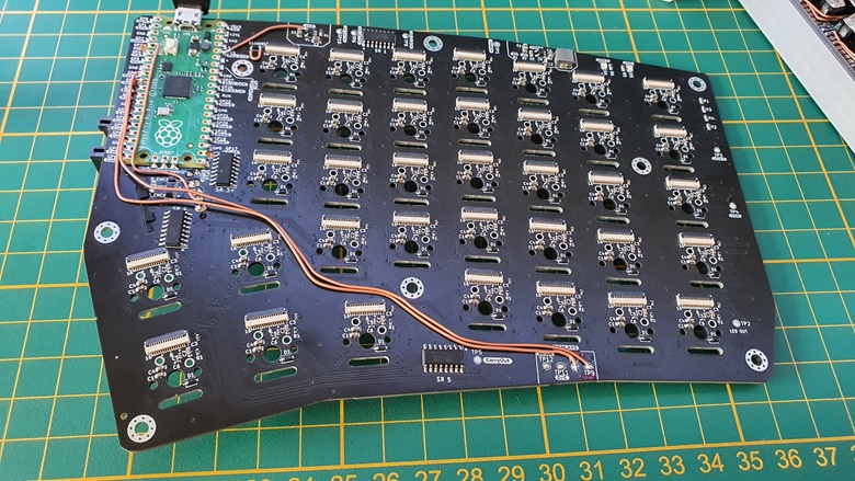
Not too bad, but definitely have to fix that for the right side. I somehow managed to exchange the SPI clock and data line and also one pin needs to stay unconnected as SPI requires to setup a MISO pin despite the fact that I have no device talking back to the MCU. With that, some pins shifted around and caused some additional bodge wires as well.
Nevertheless, with these modifications, the board was ready to drive the small displays:
Discussions
Become a Hackaday.io Member
Create an account to leave a comment. Already have an account? Log In.