 thpoll
If you have been following my blog posts, you know that a little mistake with my last PCB prevented me from using it as a keyboard: Pin 1 of all OLED displays was on the wrong side.
So I had to route half of the PCB again... Of course I took the chance to rectify some things I was not 100% happy with in the first iteration.
Right Side V2 Changes:
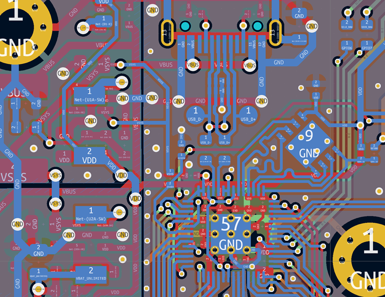
- The RP2020 and flash memory moved about 10mm away from the switching regulators as the space in between was very tight.
- The reset and boot button, as well as the debug port moved to another location as it turned out inconvenient.
- The host USB-C port got an ESD protection chip and I added a resettable 300mA polyfuse to the board to give it perfect protection in case of shorts or similar.
- The non-inverting buffers I used were actually for 5V and not 3V3 so I decided to change them with similar ones, now matching the supplied voltage (even though they worked without any issue).
- I set the current limit for the the displays and LEDs to 250mA as all displays together could potentially draw much more current (all pixel on + max brightness), not even considering all LEDs set to fullbright. Why 250mA? The USB 2.0 specification has a limit of 5V at 500mA (2.5 Watts). With both sides connected (2x250mA) and a display voltage supply of 3.7V I could reach 1.85Watts. That leaves enough room for 2 MCUs, 2 status displays, some other components and losses (also the switching regulators are not perfect). If it turns out to be too strict, I can set it to a higher value by swapping a few resistors.
- With esthetics in mind I changed the package of some components, but the IC type stayed :)
Ready? Set. Go!
I felt very confident and therefore, ordered 5 fully assembled boards with ENIG finish!
And... surprise, surprise: The boards look amazing:
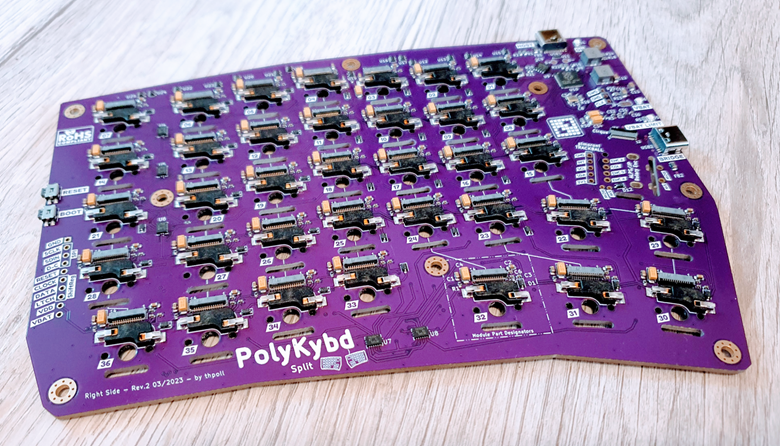
Flashing the RP2040 worked and after connecting all displays without any key switches, I could see that I didn't mess up revision 2 ;) Everything is working!! No bodge wires, no software fixes to work around hardware issues!
Professional 3D Print
Almost at the same time, the SLA 3D prints, I ordered arrived and the quality is amazing! Compared to the 3D prints coming out of my FDM printer the tolerances are a bit tighter, so I had to do a bit of tuning here and there before I could put everything together. However, it worked out and I couldn't be happier: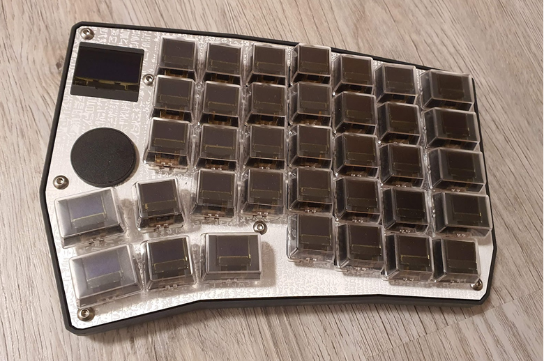
All 3d prints (case, 1U+1.25U stems, display holder and cirque holder) are designed in OpenSCAD, so fine-tuning for the next batch will be very easy. The resin parts give it a professional look and my personal impression is that it feels more like a real product :)
TA-DA!
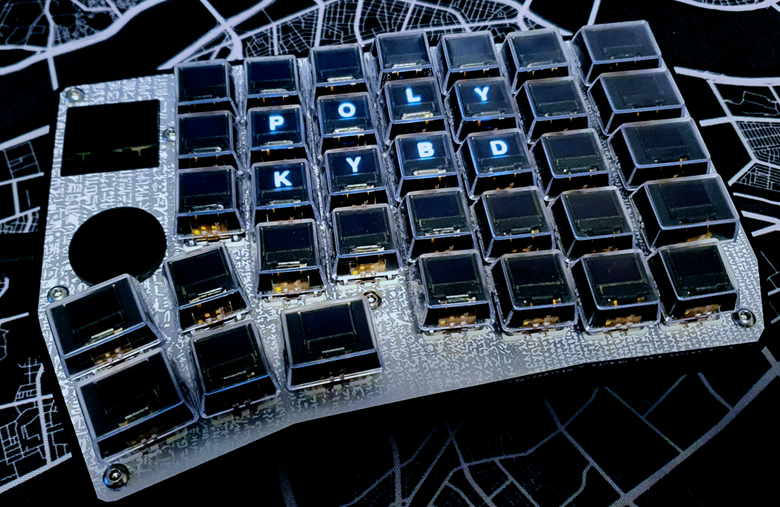
Okay, so now with displays and lights on:
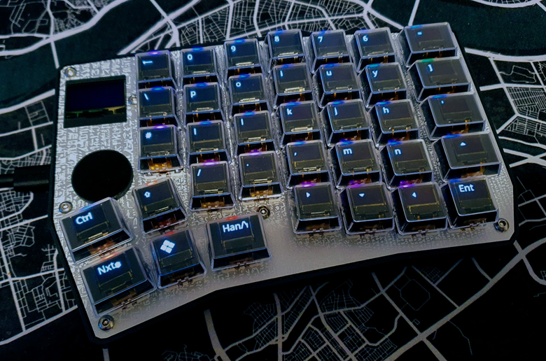
I didn't fix the displays indices yet and with that they don't show the correct content. However, I was so happy that it all worked out and just took a quick picture. There is some homework left for me!
Now it is time to bring the same changes to the left side and the hardware of the PolyKybd Split72 is ready!!
Sidenote
You might have noticed that it is really tricky to make good photos when the displays are on because those are much brighter than the environment. At some point I should maybe do some more professional HDR shots!
(until that time, I will just tweak light and contrast of my cell phone pictures)
Thanks for reading and let me know what you think about it in the comments!
Discussions
Become a Hackaday.io Member
Create an account to leave a comment. Already have an account? Log In.
Keep up the great work. Excited to see this get finalized.
Are you sure? yes | no
Thanks!
Are you sure? yes | no