About Project
OpnBeat is a low cost sampler which is simple, easy to use and fun! Thanks to its core component voice recorder chip ISD1700 series, OpnBeat is really easy to understand. There is no complex technology such as mp3 or codec. The simplicity and understandability are useful for anyone who want to modify or customize it. All that lead to fun and joy!
Reason why I started this project
I love hiphop music and become interested in sampler which is musical instrument and used for music production. But popular samplers in market was expensive and since I've never made music before, I didn't have confidence whether I was able to use it or not. Finally I reached the idea that I should make it by myself so that I could fully understand how it works and how to use it.
OpnBeat (prototype Ver.3) Overview
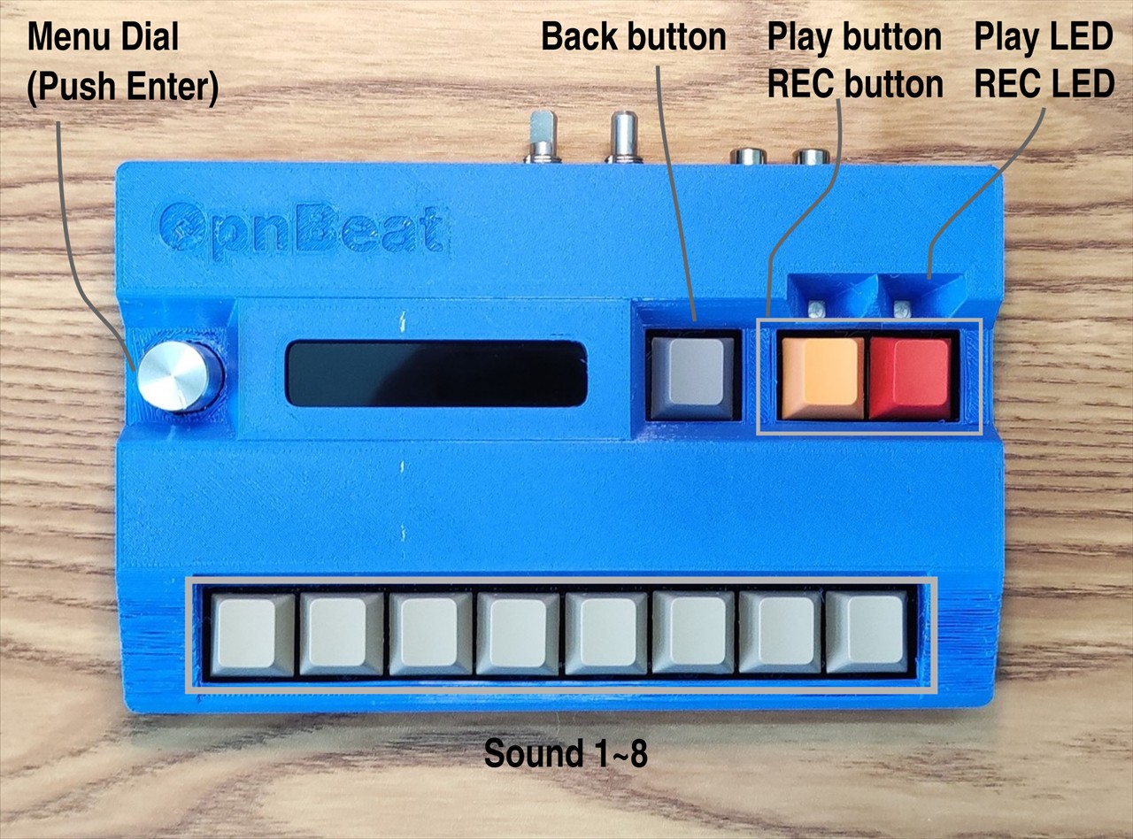
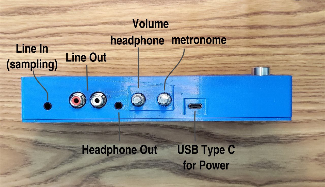
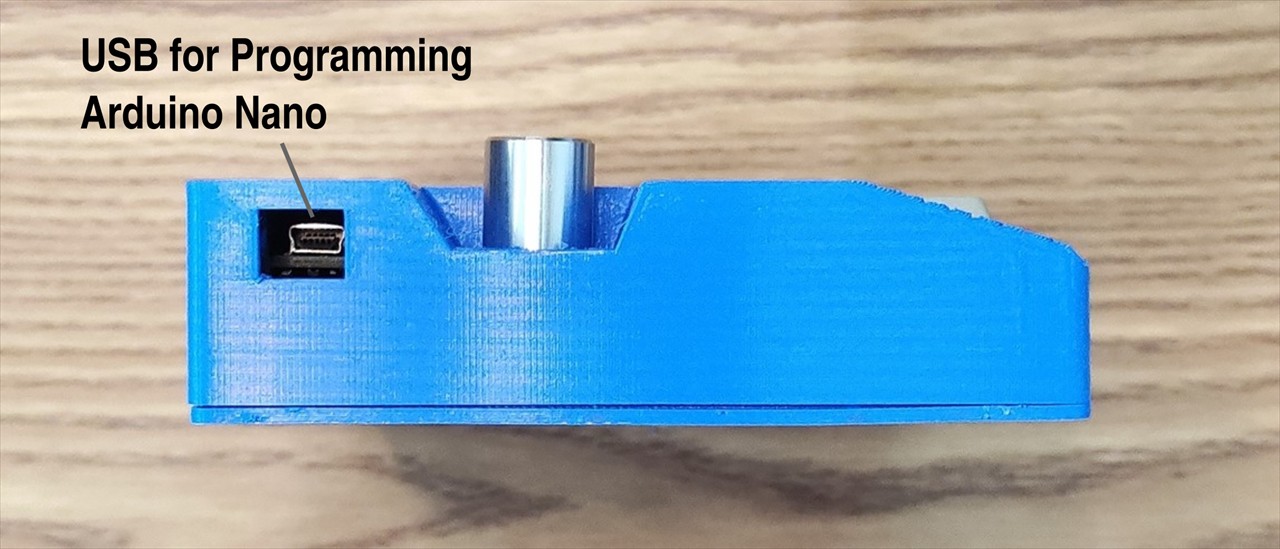
Parts and Names
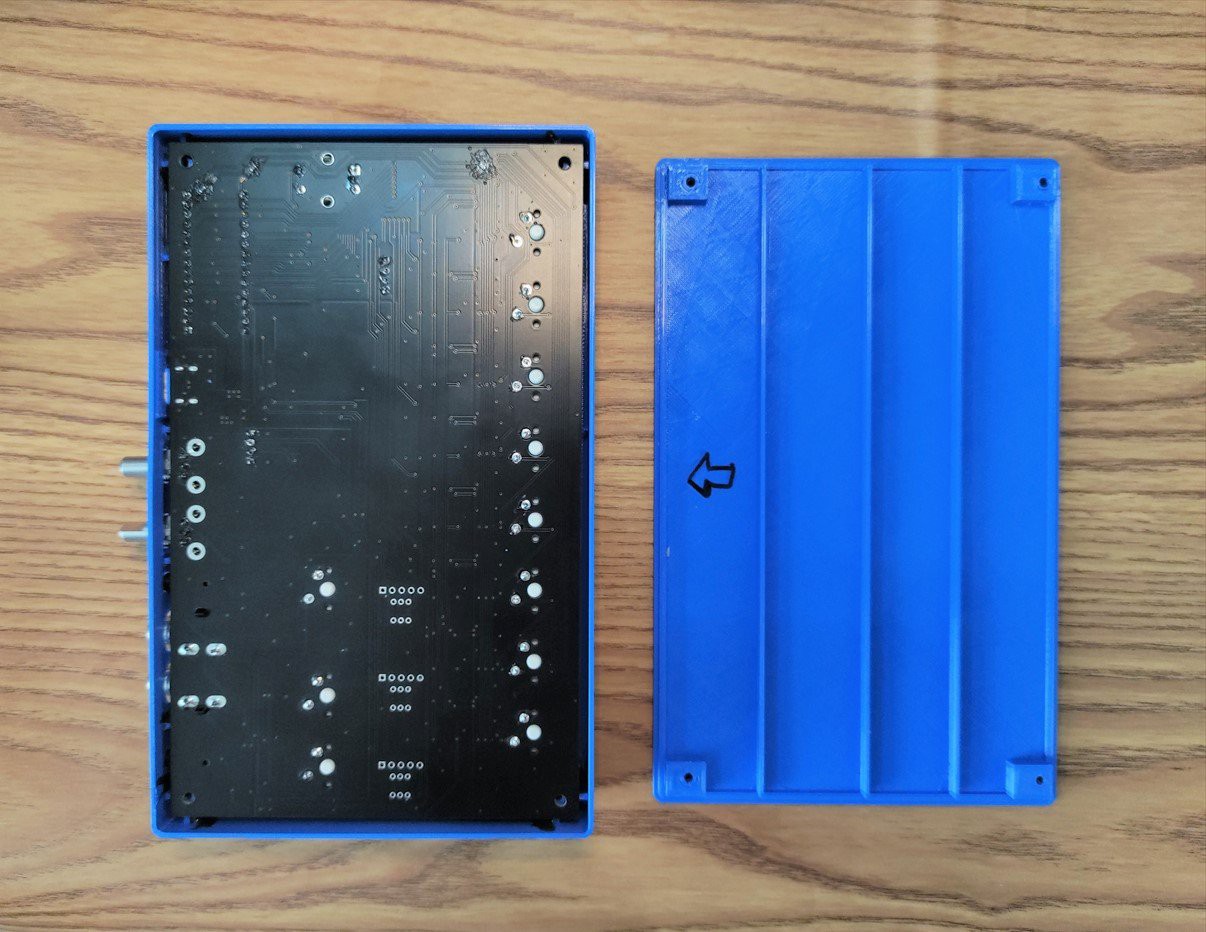
[Top View]
[Back View]
[Side View]
Demo Video
Main Features
[Functions]
- Sampling sounds up to 12 second each for 8 channels
(sampling frequency is about 12kHz, standard) - Play 8 sounds at the same time
- Play mode (real time play by keys just like music instrument)
- Sound edit mode (cut and trim sampled sound)
- Rhythm edit mode (record and memory rhythm pattern by editing rhythm in realtime)
- BPM setting
- Level setting for each 8 channel output
[Input / Output]
- 1x Line In (3.5mm stereo jack)
- 1x Line Out (RCA jack)
- 1x Headphone Out (3.5mm stereo jack)
- Volume (for heaphone, metronome)
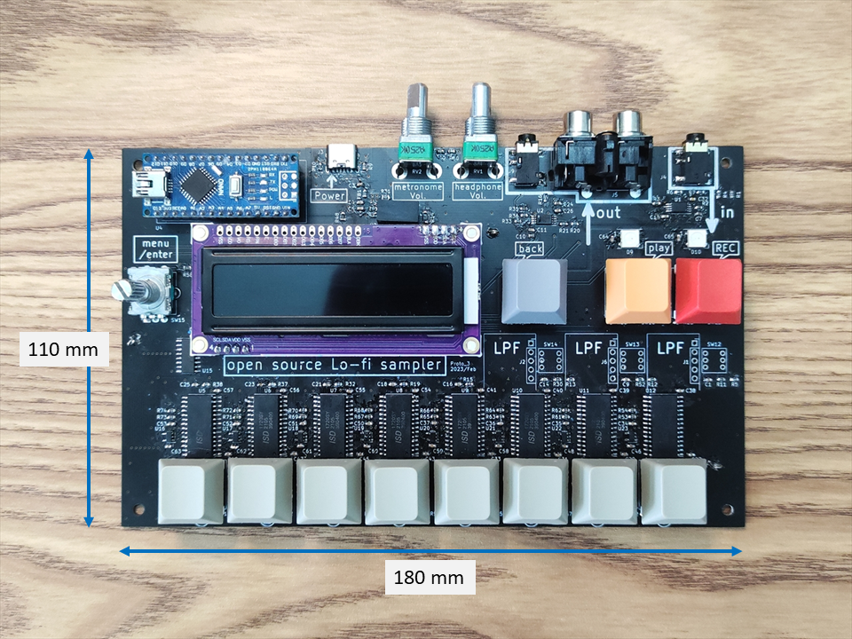
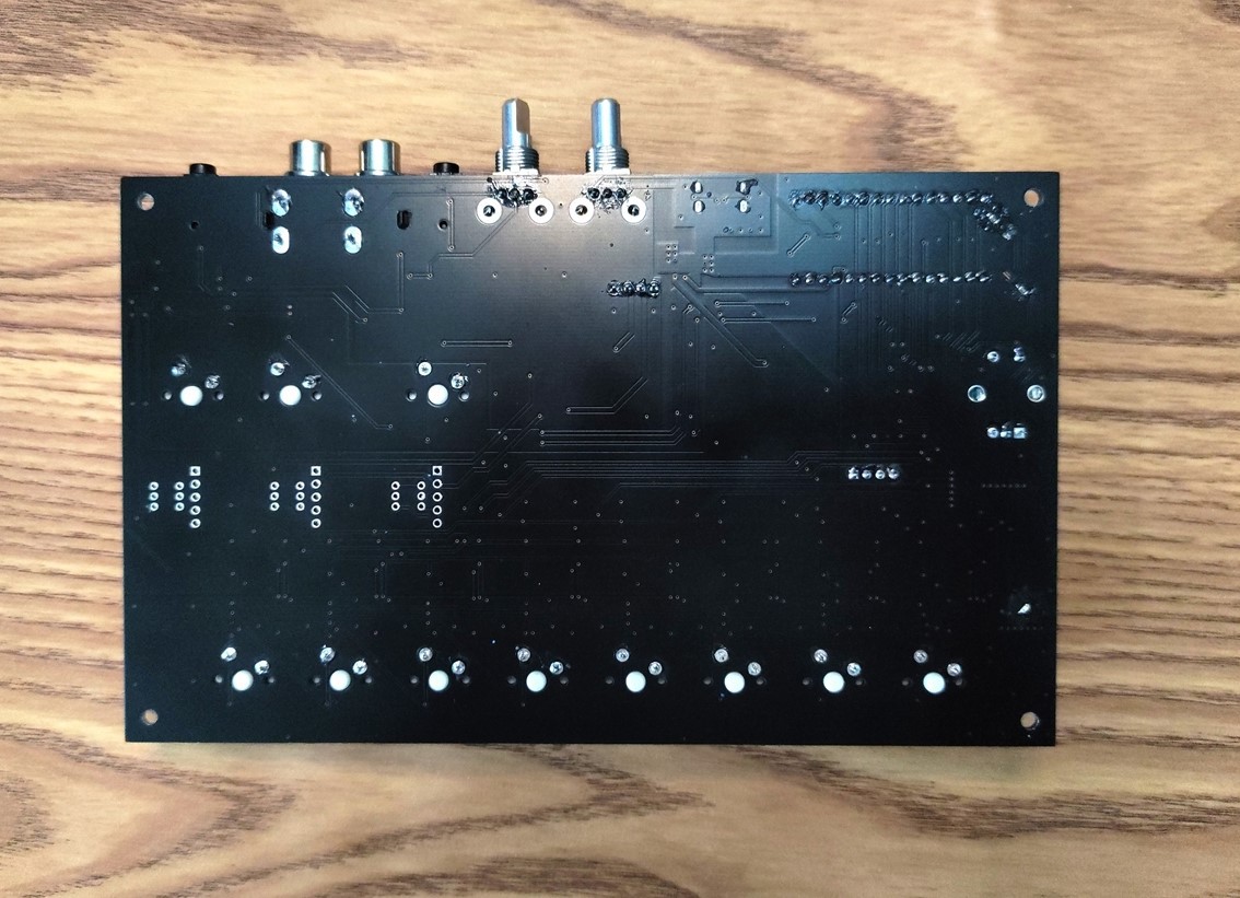
PCB
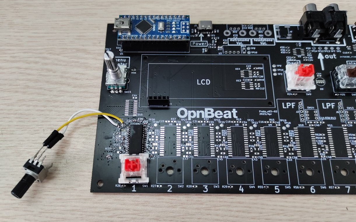
PCB size is 180 mm x 110 mm. It fits on working table of affordable FDM 3D printers so that you can make its case with 3D printer. All components are mounted on top side.
How it works
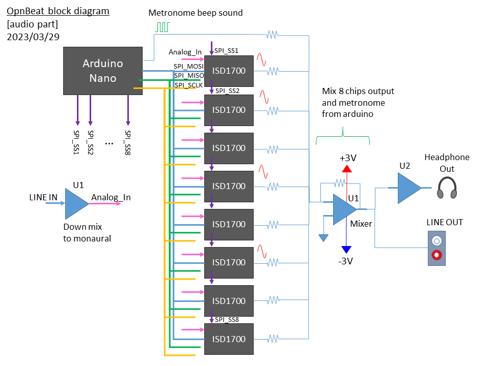
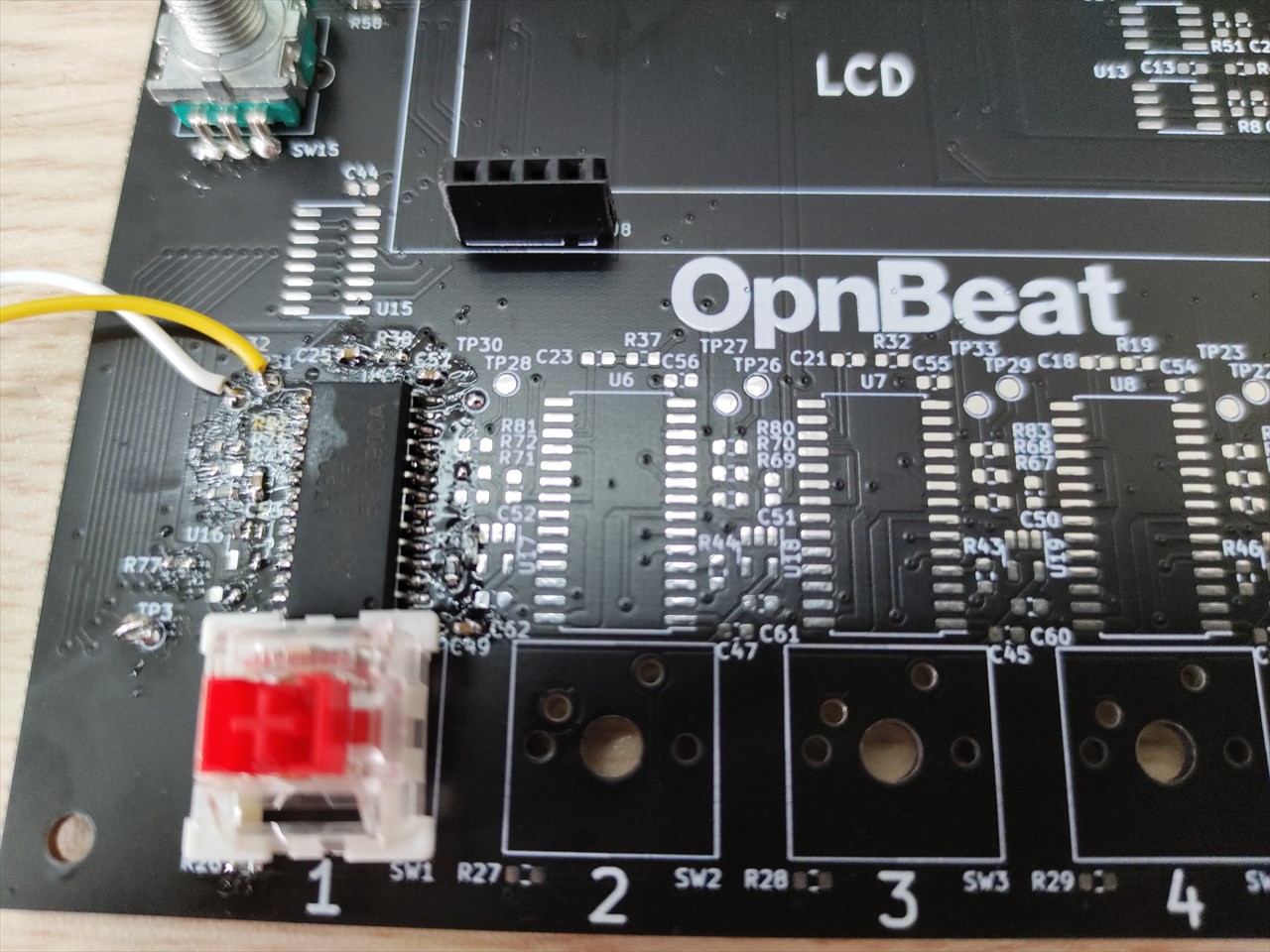
Its core component is voice recorder chip ISD1700 (in the prototype, ISD1720 is used). Usually it's used with standalone mode for simple voice recorder or toy applications. But OpnBeat uses it with SPI mode it enables full control of the chip.
Below is block diagram of audio part. In sampling sound, sound signal is input from LINE IN stereo jack, then downmixed to monaural by U1 because ISD1700 inputs and outputs only monaural sound. The input audio signal is input to all ISD1700 chips in parallel. Arduino selects only one ISD1700 chip at once by SS (slave select). So the only selected ISD1700 chip executes record, play or change volume function depending on SPI command from Arduino.
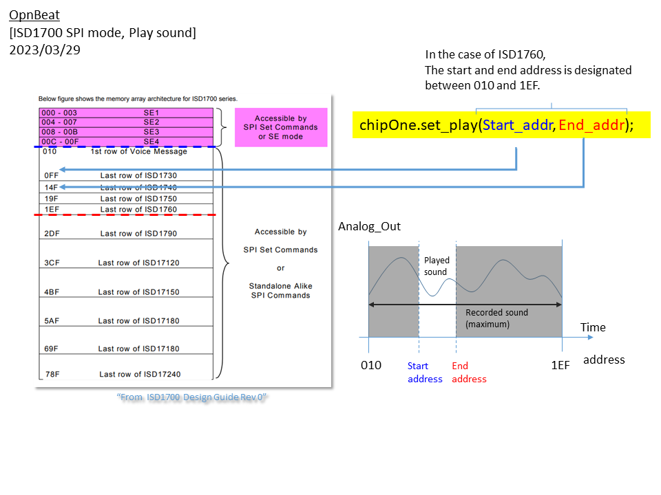
ISD1700 chip has internal multi-level storage array which records and stores input analog sound directly. It provides Direct Memory Access commands such as SET_PLAY or SET_REC which enable play and record sound segments based on designated memory address. In short, you can play only specific segment of recorded sound. The most important point is there is no need to understand complex idea such as file format or codec (e.g. .mp3, .wav) but you only have to send SPI command (PLAY/REC, start address, end address).
Each ISD1700 chips output analog sound via AUD/AUX pin which is only available in SPI mode. The all outputs from all ISD1700 chips are mixed by OPAMP (U1) and output from LINE OUT. Also the mixed signal is adjusted its volume and output from headphone out.
For example, you can use set_play command with start and end address which you want to play. Please refer below diagram to understand memory structure where recorded sound is stored. Just by specifying start and end address, you can trim and play recorded sound segment. It enables the device to trim and play only a shot of drum from seconds of recorded sound.
About sampling sound and trimming, please watch the video below (from 0:14).
Below is block diagram of controls and I/F to Arduino. A rotary encoder is for selecting menus. It uses ClickEncoder.h library. For reading 12 keys status (Back, Play, REC, encorder button, Sound1, Sound2, ... Sound8) , it uses AnalogMultiButton.h library. For LCD, it uses 16x2 LCD with I2C I/F which required only 4 wire (VDD,...
Read more »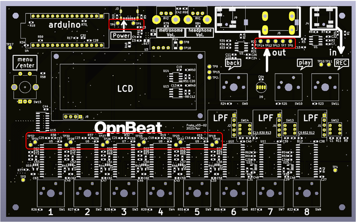
 KASSER SYNTHS
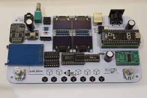
 Szymon Bartosik
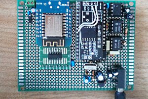
 Emilio P.G. Ficara