 Peter Sinclair
Version 2
In version 2 I explored using a single motor mechanism to feed the shuttles into the wheel. I decided that this was more mechanically complex and would require extra sensors & a continuous rotation servo or stepper to operate. I decided instead to continue building off of the V1 design.
Version 3
After testing of the hacked together version 1 I had a list of changes to make for the next version. Some of those were:
- Add tower rotation for better court coverage
- Mount gripper separately from tower so the shuttle stack does not rotate with the tower
- Pincer gripper redesign
- Add functioning trajectory controls
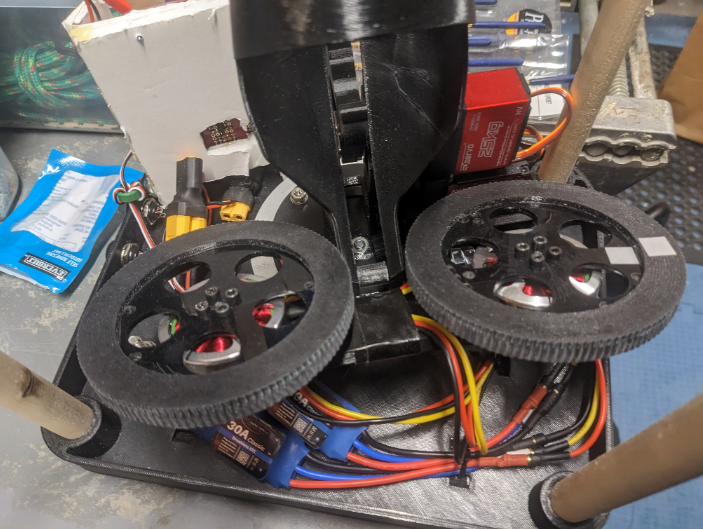
- Make proper feed wheels
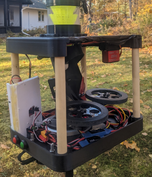
- Add enclosure
- Add stop/start buttons
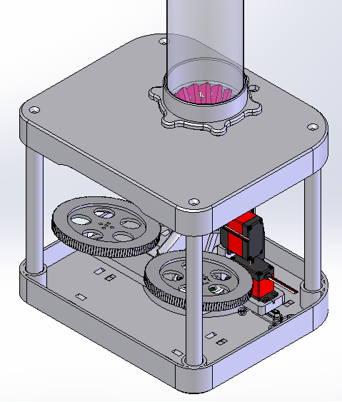
Rotation Mechanism
In order to keep costs down I started with a very low cost 4" turntable bearing from Amazon. Using a bearing minimized the forces needed to turn the unit and the large form factor provided mounting holes and good stability.
https://www.amazon.ca/gp/product/B08PBDBC6M/ref=ppx_yo_dt_b_search_asin_title?ie=UTF8&psc=1
To determine the mechanism needed to rotate the tower I first had to identify how much rotation was required. I decided that doing a direct shot to the far court corners would be a good metric as this is a challenging shot to return so would be very valuable for training. Pointing directly at the corner would allow the feed wheels to run at equal speed and give the best chance of achieving the corner shot. Since I intended to place the launcher at the service line on the far side I could calculate the angle of the launcher for a direct shot.
Court Width = 6.1m
Court Width / 2 = 3.05m
Shot Distance = Court Length / 2 + Service-to-Net
Shot Distance = 13.4m / 2 + 2m = 8.7m
https://www.dlgsc.wa.gov.au/sport-and-recreation/sports-dimensions-guide/badminton
Using trigonometry we know:
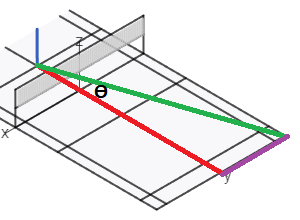
While larger angles would be needed to drop to the near-net corners I wanted to limit the movement to make guarding the device easier. I also surmised that +-19 degrees along with the direction compensation that can be achieved by mismatching the launcher wheel speeds would be enough to hit these corners. This has not yet been confirmed.
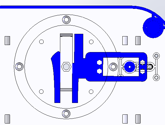
At first I considered a geared option but this would have required the servo motor to be very far away from the tower center to provide room for the gear. With a servo that can only rotate 180 degrees the servo mounted gear would need to be quite large.
Instead I decided to use a cam follower & track method which is even simpler in its construction. The servo arm has a small post mounted to it that runs inside a groove mounted to the lower plate. I kept this separate so that it could be replaced if needed and connected it with thin walls so it might break-away in case of a jam during testing.
In a future post I'll go through the basic inverse kinematics used to determine the required servo angle based on the desired turret angle.
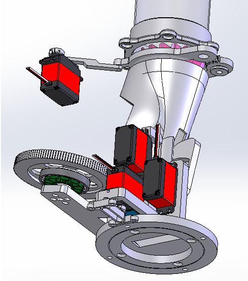
Trajectory
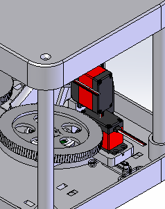
In order to allow the launcher to achieve many shot types I included the ability to change the trajectory for each shot. This should allow a high clear, drive shots, and drop shots. This was achieved by mounting the motors to a pivoting platform connected to the servo through a linkage. By changing the servo angle the platform position can be adjusted.
In a future post I'll go through the basic inverse kinematics used to determine the required servo angle based on the desired shot trajectory.
Gripper
The original gear train had a few downsides:
- Backlash - With 3D printed gears designed to be easily printed the backlash is high. Given the full travel of the grippers is only 10 degrees or so the unintended movements were quite large.
- Poor Resolution - Since the full travel was such a small amount the adjustments were quite coarse.
- Risk of overtravel - There were a lot of values that could be entered during calibration that would result in a crash since it was using such a small portion of the servo 180 travel.
- Servo Position - The servo needed to be quite far back in the launcher which limited design freedom.
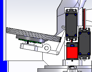
On the new design I kept the gearing between the two gripper arms, but then connected the gripper to the servo using a simple linkage.
Enclosure
To minimize print time I decided to print top & bottom plates then space them apart using wood dowels. I would then skin it with a thin walled 3D print or a lasercut panel.
Assembly
Discussions
Become a Hackaday.io Member
Create an account to leave a comment. Already have an account? Log In.