 Peter Sinclair
The wheel origins were covered in a different log but, in summary, the overall geometry is based on the Baddy open source projects' wheel with an adjusted mounting hole pattern to suit the motor and mounting I planned. I also followed Benoit's suggestion that rubber hardness should be 40-50 Shore A.
Based on the application I decided that Urethane would be best as it has high wear resistance, is readily available, and is easy to cast. Armed with these knowns I went to my favourite supply store and used their expertise to select my final products.
I used:
Smooth-On Vytaflex 45
https://sculpturesupply.com/products/vytaflex-45?_pos=1&_sid=c9445fe34&_ss=r
UVO Color Pigment (Optional)
https://sculpturesupply.com/products/uvo-color-pigment?_pos=1&_sid=41432930c&_ss=r
Release Agent
https://sculpturesupply.com/products/ease-release-200?_pos=1&_sid=91da63c13&_ss=r
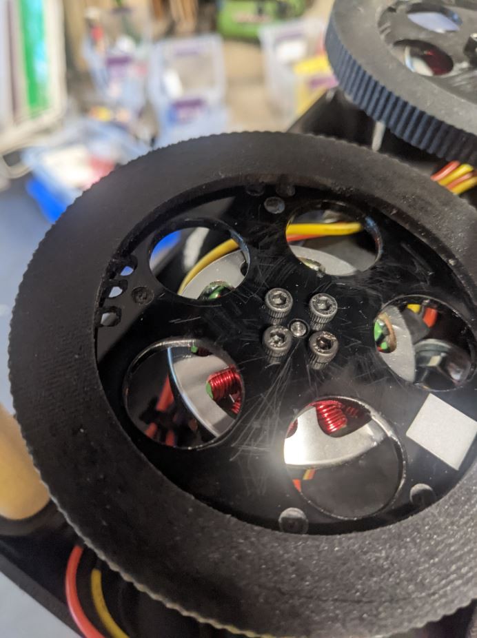
Wheel Hubs
Due to the high speed of rotation and need for balancing I decided to have the hubs laser cut out of Acrylic to ensure they are strong and solid.
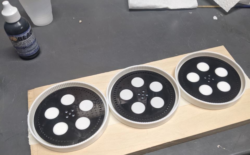
Casting
The wheel casting process was performed based on the manufacturers recommendations with the following notes:
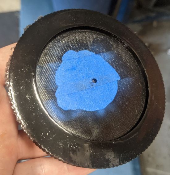
- Use painters tape to cover both sides of the hub then trim the tape using the top cover as a guide. This will prevent the Urethane from filling the larger holes as well as protect against any skin forming on the surface of the hub.
- Install the taped hub into the printed mold and install the top side cover.
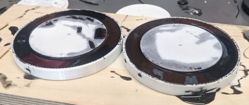
- Mix the Urethane according to the manufacturers directions. Each wheel requires about 35mL. I prepared 50mL per wheel to be safe with plenty leftover.
- Pour from a height so the stream thins out and breaks any bubbles.
Wheel Balancing
Due to the high speeds of rotation it is incredibly important to properly balance the wheel so that it can safely spin at the high RPM's. To do this I used a prop balancer to find the heavy parts of the wheel and removed rubber or rim material with a small drill bit. However, I believe this could be done more easily and more cheaply as noted in the section 'Thoughts on the Future'.
Du-Bro 499 Tru-Spin Prop Balancer
https://www.amazon.ca/gp/product/B0006N72Y8/ref=ppx_yo_dt_b_search_asin_title?ie=UTF8&psc=1
Thoughts on the Future
If I was to make new wheels I would consider changing the wheel design to cast in a mean for balancing, and I would design tooling to balance without a purchased prop balancer.
Wheel Design
I would look at casting small features into the wheel that are made to be removed. This could either be small tabs of rubber on the ID that could be cut away, or plugs that go through the hubs.
Balancer
One option would be to 3D print a prop balancer of the classic design similar to the one I purchased. However, there's another type of balancer called a pyramid balancer that could be replicated even more easily. A paperclip can be bent to act as the pivot tower while a small hub can be printed to act as the wheel center. This combined with a wheel design that can be easily adjusted would make this process much more user friendly.
Discussions
Become a Hackaday.io Member
Create an account to leave a comment. Already have an account? Log In.