LOGISIM simulator
The design was only tested on the logical level, in the Javascript simulator. Before making a PCB I wanted some form of confirmation more on the hardware level, so I entered the design in the good old Logisim.
Nowadays there is a further developed version, called Logisim Evolution. I tried it by loading one of my old designs in it. It became a big mess with long hex-sequences appended to my net names, and many shapes not displaying correctly. And indeed, Evolution is no longer compatible with the old file format. That's a pity, because I had quite a lot TTL devices converted to Logisim circuits.
So I stayed with the old version, 2.7.1, so I could use my library of TTL components. And I found a few mistakes in my design. Also found a way to save a chip on the generation of the horizontal sync pulse.
But it is slow. At it's top speed (Logisim says it is 4100 cycles/sec), when you type a short line of Apple Basic, you have to wait one minute before the prompt reappears !
PCB Finished
I finished PCB design. Here is the nice 3D preview of KiCad:

It is 119 x 150 mm (4.7 x 5.9 inch), 4 layers.
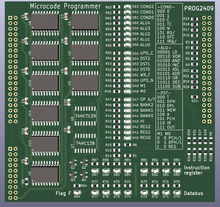
Microcode Programmer
I also needed a programming interface. Previous projects used the Raspberry Pi for that. The Pi has enough GPIO pins to accommodate the 8 or 16 bit wide Flash memories of those projects. The interface was not much more than a small universal board, with resistors for 5-to-3.3 volt conversion.
But in the Isetta the microcode flash memory is 24 bits wide. That is almost all I/O that the Pi has, not leaving enough for control signals. So now I use 8 bits I/O from the Pi. The data going to Isetta is first transferred to three HCT574-type registers (the HCT will also translate 3.3V to 5V), and then it can be transferred as one 24 bit value to Isetta. For data going to the Pi, there are three LVC244 chips to convert 5V to 3.3V. Only one of the LC244 is enabled to transfer its value to the Pi. There are two more LVC244, one for the databus and one for control signals from Isetta to the Pi.
The new RPi programmer is only required once, to program the microcode. The program for the 6502 or Z80 can reside in RAM, and can be programmed in BASIC or any other convenient language.
The Raspberry Pi has the following control outputs to Isetta:
- Disable the data output of the 3 Flash chips
- Give a programming pulse to the 3 Flash chips
- Take control of the Isetta CPU clock signal
- When it has control, send a clock to the Isetta CPU (to single-step it).
The RPi also has a few serial lines to/from Isetta, intended for character read/write so you can use the RPi as a terminal as long as Isetta has its video and keyboard interface not yet working.
Here is how it looks. Isetta connects to the left side, and the RPi to the right side. It also has LED's for the 24 microcode signals (with explanation on the pcb), and LED's for the databus and the instruction register. The LED's will also work if the RPi is not connected. It is a 2-layer board.
Discussions
Become a Hackaday.io Member
Create an account to leave a comment. Already have an account? Log In.