 Arya
AryaAt the project's beginning, when I was writing the "Features" section in the project's description, last entry was "Tons of Pi Zero-related hacks that were discovered along the way, that I'll share with you as the project goes =)". I didn't actually get to sharing any of them in 9 months' time (also because there actually weren't many I found noteworthy), so last time I was editing the project's description, I just removed that line. Now, I've been reading through hackaday.com/blog, as usual (to be exact, through email notifications that I receive for each post that comes up there - highly recommend subscribing to those). Pi Zero-based projects get there every now and then, part of them are portable projects, most of those use LiIon batteries for power - for example, SegaPi Zero does - check it out!
The small problem that I see with portable Pi Zero-based projects is - they all use a step-up, to get 5V for powering Pi Zero. When I started designing ZeroPhone hardware, one of the biggest problems was: how to avoid the stepup? Board space was not plentiful (still isn't), I don't know of many 5V-suitable step-ups that actually work well and are easy to source, and sourcing yet another part would be a PITA. Now I'm sure that, in many "Portable Pi Zero" cases, having a step-up is unnecessary, and ZeroPhone experience so far proves it.
In ZeroPhone, Pi Zero is powered from a Lithium-Ion battery directly (so, instead of suggested 5V, it's getting 3.3V-4.2V). Does it work? Hell yeah it does! It works reliably, saving power, money and board space. What follows is a wall of text that describes why I went that way, and how's that supposed to work:

One of the step-ups that I found to be highly unreliable in my previous projects
So, why even bother powering the Pi Zero directly from a LiIon battery?
- Powering the Pi Zero from a stepup is unnecessary waste of energy, due to the fact that it's doing "boost, then regulate down" conversion instead of just "regulate down" (the conversion losses are bigger). So, going without a stepup gives you more runtime for your project.
- Cheap step-ups tend to be unreliable. You can source a more expensive one, from Adafruit/Sparkfun, but you might as well use that money on something that'll be actually useful for your project.
- Stepups take up space in your project's case (in my case, a stepup would take up board space).
What are the disadvantages?
- You need to track the battery voltage. You do need that even when you're using a stepup, just that with a stepup it's easier to overlook (but also easier to run your battery beyond the safe limit).
- You'll still need a stepup if you need to power random USB devices.
Here's where I started with this topic - people on Raspberry Pi forums reporting success with powering the Pi Zero from as low as 3.3V. Let's take a look on the small part of Pi Zero W schematics, to be exact, a small part of a small part of the schematic:
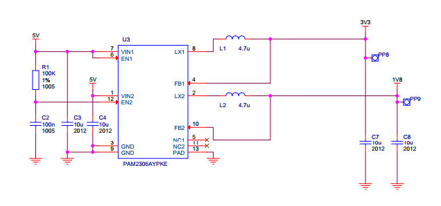
5V on the left is what we get from, usually, the USB port, and 3.3V & 1.8V on the right are what's used for the CPU, peripherals and whatever else needs to be powered on the Pi Zero board. We need to see if we can replace the 5V with 3.3V-4.2V, and to see if that's possible, we need to know where 5V is used. So, the parts where 5V appears are:
- The PAM2306 regulator (wired according to the schematic right above)
- USB ports - in case of a Pi Zero, there are no protections or anything, the USB ports' VCC is wired in parallel.
- 40-pin header - pins 2 and 4, also in parallel
- HDMI port's VCC - through a diode (to avoid backpowering the Pi through the HDMI port)
- BCM2835 built-in voltage regulator:
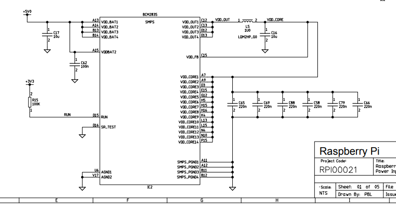
The built-in regulator uses the 5V to generate the VDD_CORE voltage, to power the CPU itself.
Again, LiIon voltage is going to range from 3V to 4.2V. Which of the mentioned components are OK with this, and which aren't?
- The PAM2306 claims Vin range to be from 5.5V to 2.5V. However, the version of the regulator, evidently, is a fixed-output version, and one of the outputs is 3.3V - as PAM2306 doesn't have boost capabilities and isn't even wired to be able to boost anything, What's the minimum voltage we have to feed it, then? Well, this graph from the datasheet says it's tested to work with 3.5V while fixed on 3.3V:
![]()
With this, and the fact that regulator claims to have 100% duty cycle operation capability, let's say that the resulting range is 3.4V-4.2V - well within operational capacity of most rechargeable LiIon batteries (not talking about LiFePO4 or other, even more exotic breeds) - Are USB devices compatible with 3.4V-4.2V? Even though USB specification defines USB VCC as voltage in 4.75-5.25 range (IIRC), some devices don't actually need that much - many feed 5V into a linear (sometimes switching) regulator that drops the voltage to 3.3V, or even less. I've had success with running CP2012-based USB-UART dongles, USB-ISP dongles, even WiPi dongles and some other devices (like flash drives and USB hubs) from 3.4V-4.2V. I definitely wouldn't attempt to charge a smartphone from that, though - that's where those 5V are actually necessary (since battery chargers in phones aren't designed to operate from LiIon voltage, they'd need a step-up to keep up with the 4.2V CV step requirement). tl;dr - here's where having a step-up is actually economical. I also wouldn't power a USB 3G modem, for instance.
- 40-pin header on Pi Zero is blocked by ZeroPhone boards, from both sides, so you can't actually plug a HAT that could require 5V ;-) On both front and back boards, there are no devices that actually require 5V - most of them either work from 3.3V, or from VBAT.
- HDMI port's VCC is designed to power an EDID EEPROM (so that the monitor's characteristics can be read from it), or a HDMI-to-whatever adapter. Well, by now, I'm sure that none of EEPROMs used in more-or-less modern monitors actually require 5V - the 5V-only EEPROMs seem to have become obsolete, since it's not exactly economical to produce them, as compared to EEPROMs that accept a wide range of input voltage. Anyway, it's a requirement mismatch, and I don't have an opinion on the adapters - they might as well require 5V and not a volt less.
- I don't remember anymore where, but I've read, either in some Raspberry Pi documentation that has since vanished, or on Raspberry Pi forums, that the VDD_BAT accepts a wide range of voltages, including the LiIon battery range (which makes sense, since the voltage it has to output is pretty low, about, what, 1V?)

So, there are problems with powering USB devices, and possible problems with HDMI. There are, actually, more problems:
- It's bad practice to power something from a LiIon battery while the battery's being charged - that can lead to the charging cycle never finishing properly, essentially, whatever you're powering will be powered from the charger, and it's going to be, at best, confused about that. I've heard something about potential for the battery to be overcharged, I don't understand the topic enough to confirm that's a possible consequence, but that is something to be on the lookout for =)
- There has to be a low-voltage cutoff, so that. at a certain point, if the charger is not connected and the battery voltage is too low, everything's powered down until battery gets back up again. The charging&protection circuit has a 2.5V cutoff, but that's not good enough - the Pi Zero will go into a cyclic reboot long before that.
- If you're powering a Pi Zero from LiIon voltage, you need to take care to not connect 5V in parallel, that is, if a battery is connected to the 40-pin header of a Pi Zero, do not connect a MicroUSB cable with 5V to the Pi Zero's USB ports! Best case is battery's protection circuit will trip (that's why I highly recommend you have one). ZeroPhone solves this by making MicroUSB ports on the Pi Zero inaccessible, hiding them behind a 6-pin header that connects the front and the back boards.
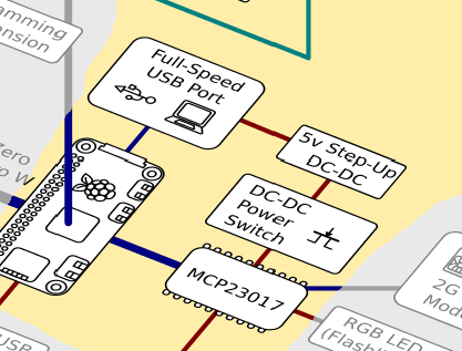
How does ZeroPhone solve those problems? What else is necessary to make it all work as good as it has to? Let's take a look at the block diagram:
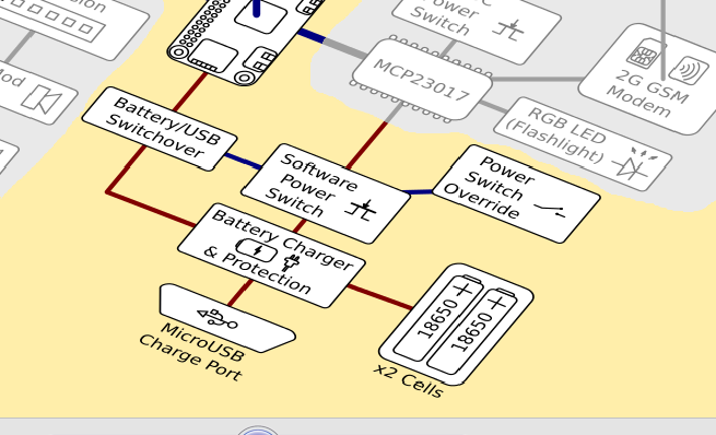
There are two operational modes to take into account - when a ZeroPhone is powered from LiIon batteries, and when it's connected to a charger. When it's connected to charger, it's in our best interests not to continue powering everything from the battery, as the battery won't be able to charge fully. So, the "battery/USB switchover" block is responsible for that. Here's how it looks:
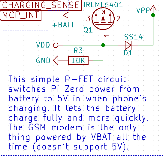
Here's an in-depth description of this circuit. Effectively, when a 5V charger is connected to a MicroUSB port, the Pi Zero is actually powered from 5V, so it doesn't load the battery and it can charge in peace (the GSM modem, on the other part, is connected straight to VBAT, since it can't tolerate 5V - haven't yet found a good way to solve that, but the charger still seems to be able to finish charging the battery just fine). This also works as a workaround for any possible problems with HDMI power - if a device requires 5V, you can work around it by plugging ZeroPhone into a charger, so that the HDMI voltage will rise to 5V.
Now, about "software power switch" block - it shuts off the battery from the system, and it's controlled from the Pi Zero. Its main function is to work as a low-voltage cutoff. The idea is simple - on Linux side, there's a daemon that tracks the battery voltage (which is available from two sources - from the GSM modem and from the ATMega, which has system voltage available through a resistor divider). There's no software support for this switch yet, though - the daemon capable of such a thing is not yet written, main reasons for it are: 1) the GSM stack is not yet integrated into ZeroPhone software, so there isn't yet a consistent way to expose GSM modem's battery voltage tracking capabilities 2) ATMega firmware doesn't yet expose the battery voltage 3) there has to be some kind of UI to notify the user, and pyLCI doesn't even have notification support yet, not to mention a home screen, where you could show the battery icon. However, we'll get there eventually =)
Now, about powering USB devices - that's where a step-up is, unfortunately, indispensable in a setup like this:
However, on ZeroPhone it's only enabled when it's actually necessary to have 5V for powering something, due to the fact its power is controlled from software, due to the power switch - so energy still isn't wasted =)
So, you don't want to read all this, and you want to power your Pi Zero in a more efficient way, so that you get that additional hour or two of runtime. What are the requirements, and what are my suggestions?
- Make sure you're using a protected battery, or have a protection circuit on the charger breakout you're using. If it has separate contacts for OUT+/OUT- and B+/B-, you likely do have a protection circuit on the charger breakout, otherwise, use a separate protection circuit, or one built into your battery (if it has one). This requirement applies even if you're not using a stepup.
- Use a switchover circuit, it'll allow your battery to charge fully, and will help in case there are problems with HDMI. It's simple - one P-channel MOSFET (I use IRLML6401), one Schottky diode (I use SS14, I guess 1N5819 would work too) and one resistor (10k works well for me). If you don't want to source parts and solder it yourself, I have 20 small boards with those components already on, that I can sell for $5/each (excuse me while I go and open a Tindie store with these, but feel free to PM me to order one or two before it's set up =) ).
- If you have an accessible USB port, that's where you actually need to have a step-up. Otherwise, you need to make sure that the USB devices you're powering is compatible with this voltage internally (though, worst case is, it just won't work).
- Make sure to not connect cables with 5V on them to MicroUSB ports if a LiIon battery is connected to the 40-pin header, and vice-versa.
I guess this is why I haven't done this writeup before - because of all the text I had to write to make this article as good as I wanted it to be. Regardless, I do hope this helps to creators out there, those who want to make Raspberry Pi-powered portable devices, just like I do =)
Discussions
Become a Hackaday.io Member
Create an account to leave a comment. Already have an account? Log In.
Thanks for this write up! Great info here.
Are you sure? yes | no
I have been trying to power a Pi Zero W (wifi disabled) using a fully charged 3.7V 14500 Lithium battery. I'm not super tuned up on battery specs, but my understanding is that it should put out enough current to boot the Pi, maybe 150mA but (I think) less than 200mA. What I am seeing (V+ connected to either 5V pin or 3.3V pin, the result is the same) is the cyclic reboot mentioned in this post, and the current draw pulls the battery voltage down to about 3.1V. The normal on time for this project is only about 30 seconds, followed by long periods of inactivity so the sustainable current for the battery is the more pressing spec than the total energy capacity.
Before I make a trip into town to buy a 18650 battery I would like to ask whether
1) the 14500 battery really is undersized for this project, and I should really be using battery XXXXX. This particular project needs to be very compact, so I am inching my way up the battery-size ladder to find the smallest battery that will work.
or
2) I'm doing something wrong (V+ applied to the wrong place on the Pi board, for instance) which is causing the Pi Zero to pull more current than is necessary.
Thanks very much,
Are you sure? yes | no
https://www.youtube.com/watch?v=gVp5JCB-N2M for a video
Are you sure? yes | no