 Kārlis
Frame
The frame is mostly made from 700mm and 200mm 2020 aluminum profiles and various brackets. Then end plates where initially made with hand tools and a drill, but later versions are laser cut. This was still at the time when I tried to avoid 3d printed parts. If you are considering to reproduce project you might want to redesign them, to match the fabrication tools and techniques available to you.
If you are considering to order them from a laser cutting service, they can be ordered as two pairs of identical parts. And afterwards cutting a rough hole in one of them for the motor.
Drive rollers
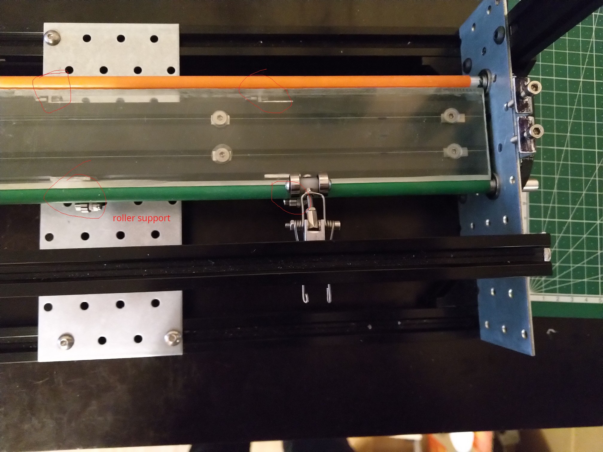
Note I know that many plotters work push and pull with single line of rollers and it works assuming the rollers are sufficiently close to the tool, when using a thick material or light tool pressure. But the current roller size is limiting how close I can get support surface and tool movement line. And in some of the the earlier single roller tests (not having top rollers engaged) I did observe paper pushing up against the tool, which didn't happen when both side where pulling. I will be doing more tests to find out which combinations of material and tools need or don't need both rollers.
First version of drive rollers where made from 8mm aluminum rods wrapped in long balloons (the ones used for making balloon animals). Getting the balloon on the metal rod was a bit tricky. I tried soap water but it didn't work very well and also caused the rubber to spin more easily which is something you don't want. The method that worked best was: filling the balloon with air and letting it to sit for while, inserting tube slightly bigger than in the rod in the neck of balloon while its still filled, and then quickly inserting the rod through the tube before the air fully escapes and balloon fully shrinks. After quickly releasing air for short time balloon will be in partially stretched out state, in combination with any air that might get trapped it will help with the process. Once balloon is evenly stretched across the metal rod open cut open the end and push out any remaining air bubbles.
As mentioned before at 700mm length without support everything bends especially thin aluminum rod. So the every ~10-15 cm the rollers where supporter by pair small bearings. It was quite tedious to align all 12 of them.
Balloons where very grippy and worked well from that perspective. But they where quite fragile. One of the causes of it breaking was rubber gripping the paper better than aluminum resulting in it stretched and pinched. Other common cause of breaking was edges of support rollers cutting it.
After rubber balloons I tried rubber tube. Whatever the local hardware store had at appropriate size (probably pvc). It was more slippery than balloon, but that wasn't the bigger problem. After sitting idle for while both the top rollers and support rollers made dents in the spots they where resting. This caused rattling when the rollers where spinning.
I also tried wrapping the aluminum rod in various tapes, but that also was very noisy as the rollers crossed joints in the wrapping of tape. Those test pretty much eliminated the idea of bottom supporting rollers.
In the current version I switched to steel rods and placed a KP08 bearing block in the middle, which means ~350 mm of unsupported length. The bearing block in the middle increases the requirements for roller diameter to ~30mm. So the current approach uses 30mm aluminum tube with 3d printed endcaps wrapped in 180 grit sandpaper.
After thinking about this more, now that I have switched to larger radius tube, it flexes significantly less compared to 8mm solid rod. The middle support might not be necessary anymore.
Top rollers
Main purpose of top rollers is to press the paper or cutting mat against active bottom rollers without adding any additional friction or resistance.
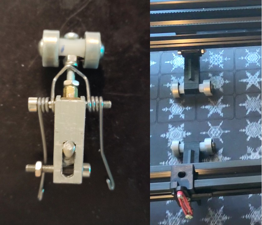
On the left one of the earlier versions using a selfmade double torsion spring and a pair of bearings. The mounting mechanism allowed adjusting the position left to right (based on current material size), front/back for positioning above bottom rollers, and rotating to align parallel with bottom rollers. Alignment with bottom rollers turned quite problematic. Even very small mistakes for the angle caused it to push the paper sideways. With multiple rollers each pushing in slightly different direction it resulted in paper bunching. It was a problem mostly for thinner paper, less for cardboard and cutting mat. Wrapping the bearings with UHMW tape to reduce the sideways frictions, seemed to help and reduce the bunching up. While it was possible to disengage the springs by unhooking the ends if not done carefully (which happened often) the ends snapping down could easily make a hole in paper. Other problem with this design was that changing x position ruins the alignment.
The later design uses a small lever for lifting/and lowering the arm with roller. Which makes it a lot more convenient to use. Torsion spring replaced with rubber pulling the end of arm with roller, a lot more similar to design used by some of the commercial vinyl cutters. It also makes it easier to adjust the force by doubling the rubber or using a different hole for the screw holding one end of it. Left to right position changes are also much easier because the whole roller assembly can freely slide sideways on the aluminum profile while the rollers are lifted. There is no angle adjustments, but combination of 3d printed parts being more consistent and possibly other factors seemed to make this less of a problem. Biggest issue with current design is that the bolt holding lifting lever gets loose sooner or later. Not surprising since using bolt for that purpose isn't really appropriate.
TODO: do some tests with softer top rollers. Most roller systems use soft rollers at least on one side as that increases contact are and thus grip. Soft roller would likely be less slippery than the current ones, thus possibly making the sideways steering problem worse, but the increased contact area with bottom rollers might negate this downside.
Support surface
Between the the rollers there is a surface supporting the paper while the pen or blade are doing their job. Initially with the smaller rollers there was enough space for 20x40 profile but with the bigger rollers there is only space for single 2020 profile. It needs to be cut few millimeters shorter than 700mm based on the thickness of end plates unlike rest of the 2020 profiles used in the build. You can get 2020 profiles that have one of the 3 sides flat without the slot for T-nuts.
The top surface of it is covered with UMHW(-PE) tape. It reduces sliding frictions, and also saves the surface and blade when cutting without a cutting mat and blade depth is set too deep. Supposedly commercial plotters are using a PTFE based strip for even less friction. But UHMW tape seemed easier to get at least when I was trying to buy it. Search results for PTFE tape often being filled with thread sealing tape doesn't help. In some of cutting tests I even used cheap electrical tape, this probably isn't too critical.
Tool head
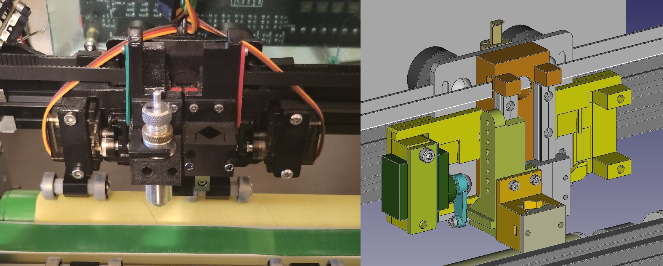
Tool head consists of two symmetrical parts allowing to use either two pens or a pen+blade without having swapping tools. Two halves are positioned as close as possible to each other to maximize the area covered by both tools. Up and down movement is performed by a small hobby servo.
Tool mounts are split in two parts. First part mounts to the vertical rails and contains everything related to vertical movement (holes for hooking one end of rubber, surface that servo pushes up). Second part mounts to the first part and hold the actual tool. This allowed designing the tool mounting independently from vertical movement part and also reduces the wear on threads in the linear bearing carriage as I keep swapping out different kinds of tools.
Due to limited width, tool mounts are not symmetrical and need to be mirrored depending on whether they are for left or right side. Having tools mounted off center somewhat negates the purpose of having vertical rails mounted as close as possible to each other.
Servo arm supports the slider with tool from bottom and is also connected with a rubber. That way when pushing up force is transferred directly. But when moving down force depends on how much the rubber stretches. Main purpose of it is compensating for surface imperfections, cutting surface not being perfectly parallel to x axis and applying roughly fixed tool pressure based and how deep bellow surface you try to move it. As unintended benefit, in case of crash, force is limited by maximum stretch of rubber instead of motor holding torque or belt slipping.
In theory this allows adjusting force with software. Although wider range of force can be more more easily achieved by physically changing the configuration of rubber (number of rubber bands, on which hole the end is hooked, making multiple loops). For maximum speed you want the vertical movement to be minimal, barely lifting the pen above paper, and moving down only enough to compensate lack of flatness, and generate most of the force with preload.
Near the end of servo movement range movement is almost perpendicular to the vertical forces. This gives a mechanical leverage reducing required holding torque for a fixed force and increasing maximum force available. End of the movement range is also the point where you need the most force, since it is proportional to the stretch in spring/rubber. As with any mechanical leverage it comes at the cost of increased travel distance. When using a pen which doesn't need as much force, you can position it in the middle of movement range where the vertical speed is highest.
I considered using an approach where single stepper motor controls vertical movement similar to how LumenPnP https://github.com/opulo-inc/lumenpnp/ does it, but decided against it.
- Single stepper motor is much heavier than 2 hobby servos -> more weight harder to accelerate
- requires a limit switch, and homing procedure
- moving the z axis in either direction results in one of the tools moving one of the towards surface, safe state is in the middle of range. This complicates software to operate safely without crashing a tool.
One more different approach that was considered was using solenoids for vertical movement. They could potentially provide very fast movement. Solenoid might also remove the need for rubber/spring based joint. Maximum force rapidly drops outside the end of range. Most of the solenoids are not rated for continuous operation, meaning you either have to run them at low current further decreasing force or use a beefy one which would be somewhat heavy. It might be possible to improve it by using maximum current only during initial energizing and then decreasing it during continuous movement. Although the current is necessary not only for holding it in position but also applying enough force.
An alternative to controlling force with a spring or rubber is gravity. Its much easier to get fixed force using a matching weight and it isn't affected by vertical movement or material thickness. Major downside to this is that the weight needs to be accelerated along x axis during movement. This might be fine for many pens or fine liners that need barely any force. Some quick tests by trying write on kitchen scales indicate that many of them work well in 15-60g range. But some ballpoint pens or making a thick line with pencil can take 120-160g. And cutting vinyl or cardboard with a blade can take the equivalent of 200-600 grams of force or more. Attaching 0.5kgx2(for two tools) just as weight is not something I would like.
I should probably experiment a bit more with weight based approach for pens. Luckily the current design permits that by simply removing rubber, and hanging some weight on the end of pen. I wonder whether the small forces that I could get away with while writing by hand would work reliably for plotter. It might take a bit more force to prevent. Humans have the benefit of adjusting based on what they see and sometimes even repeating.
Electronics and wiring
Nothing exciting here. For now using a BTT octopus as the controller board. It's an overkill, but since I initially wasn't sure about all the details, wanted to make sure there will be plenty of extra pins. The wires for tool servos are held in air using a pair of 1.75mm 3d printer filament. The plastic filament retains some of it's shape from previously being on spool, it requires a bit of trial and error to choose correct mounting direction so that it bends without tangling up.
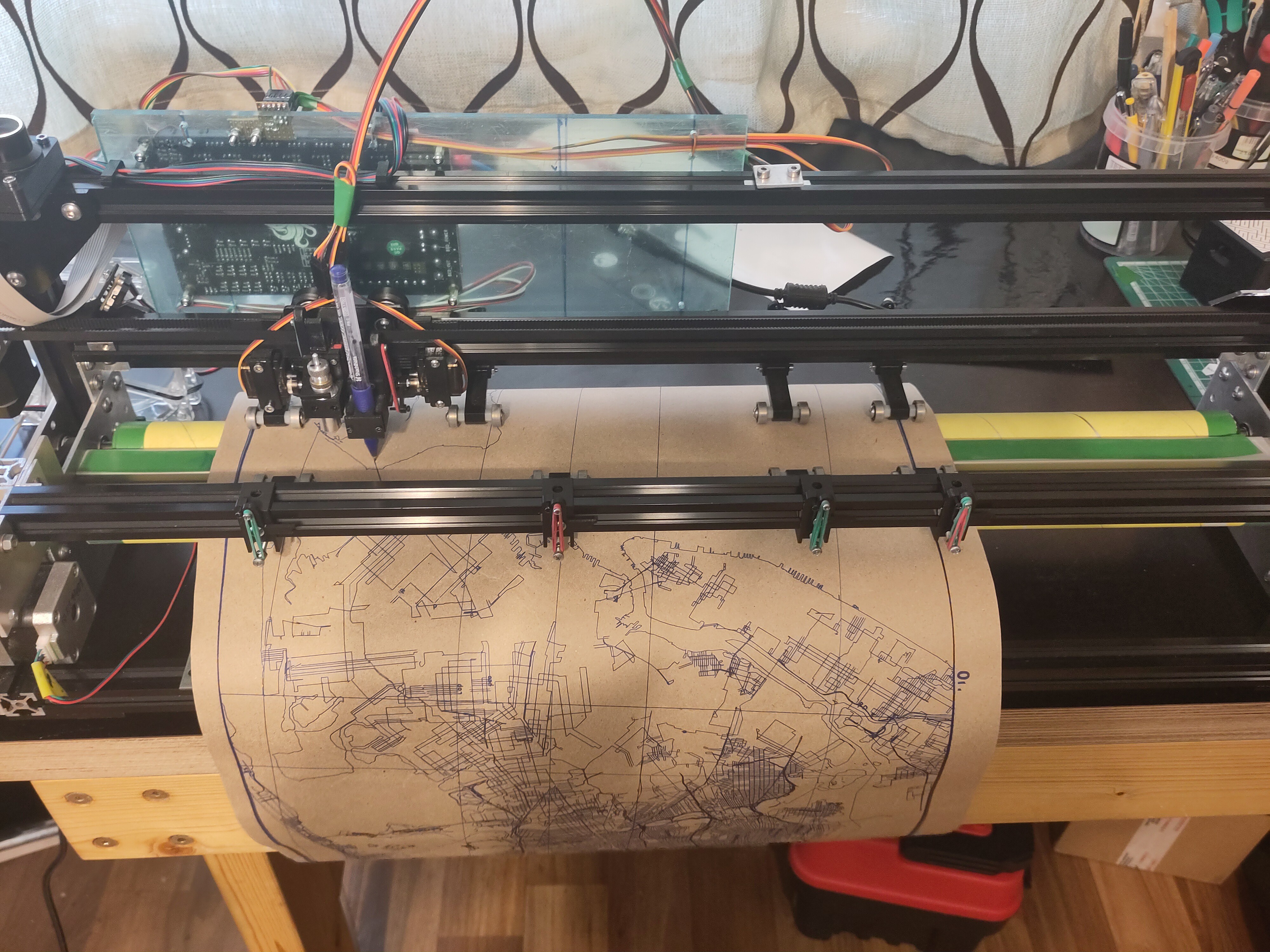
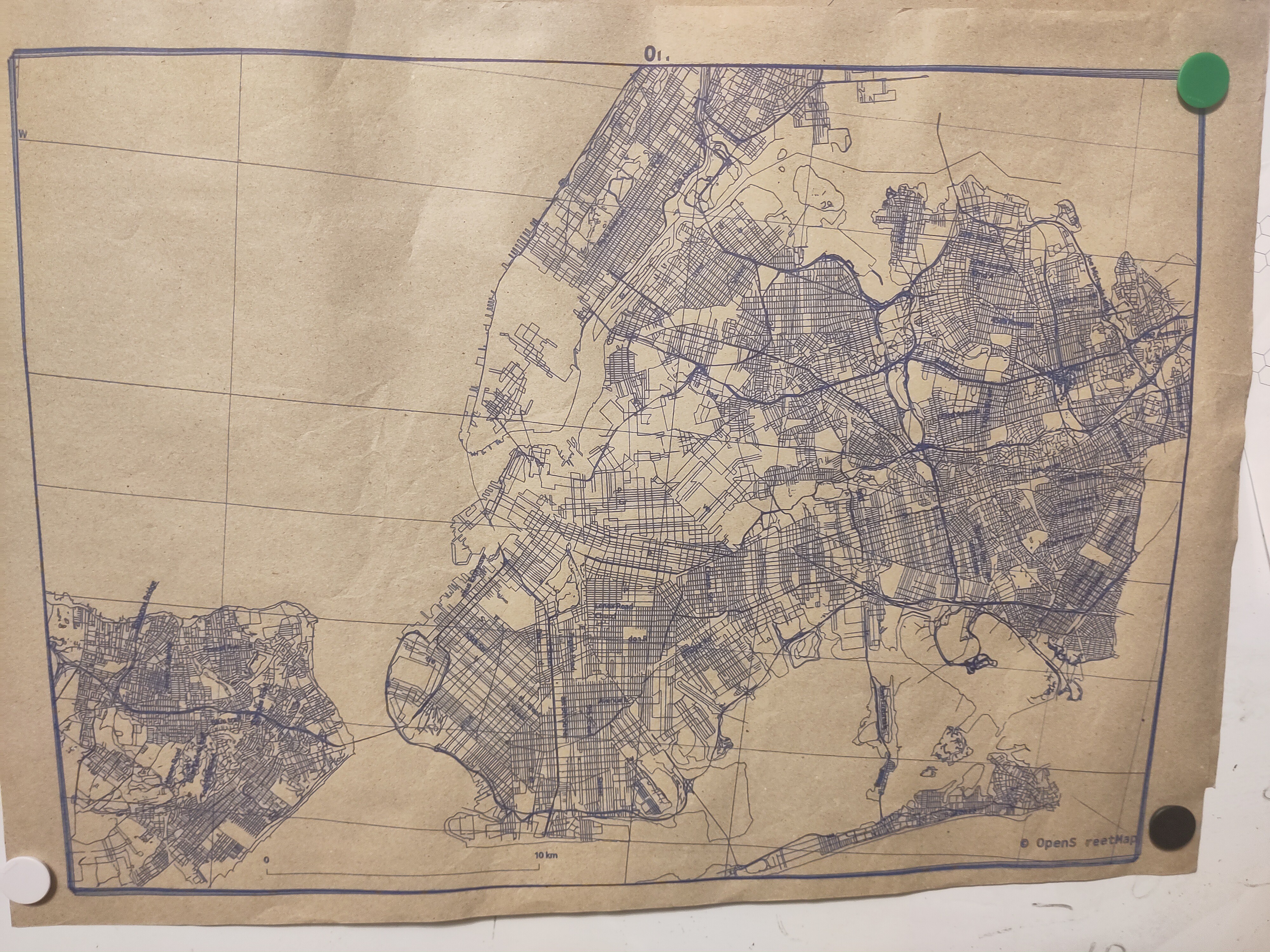
Bonus picture
1:100000 A2 map of New York. At the start when drawing frame, position shifted by 5mm, didn't observe additional large shifting during rest of the job. Will have to try repeating it, as this isn't the first time when shifting happens during initial frame drawing.
70% into the job, servo died. It was one of cheapest servos available so I am not too surprised, although I hoped it to last a bit more.
Discussions
Become a Hackaday.io Member
Create an account to leave a comment. Already have an account? Log In.