 Dr. Cockroach
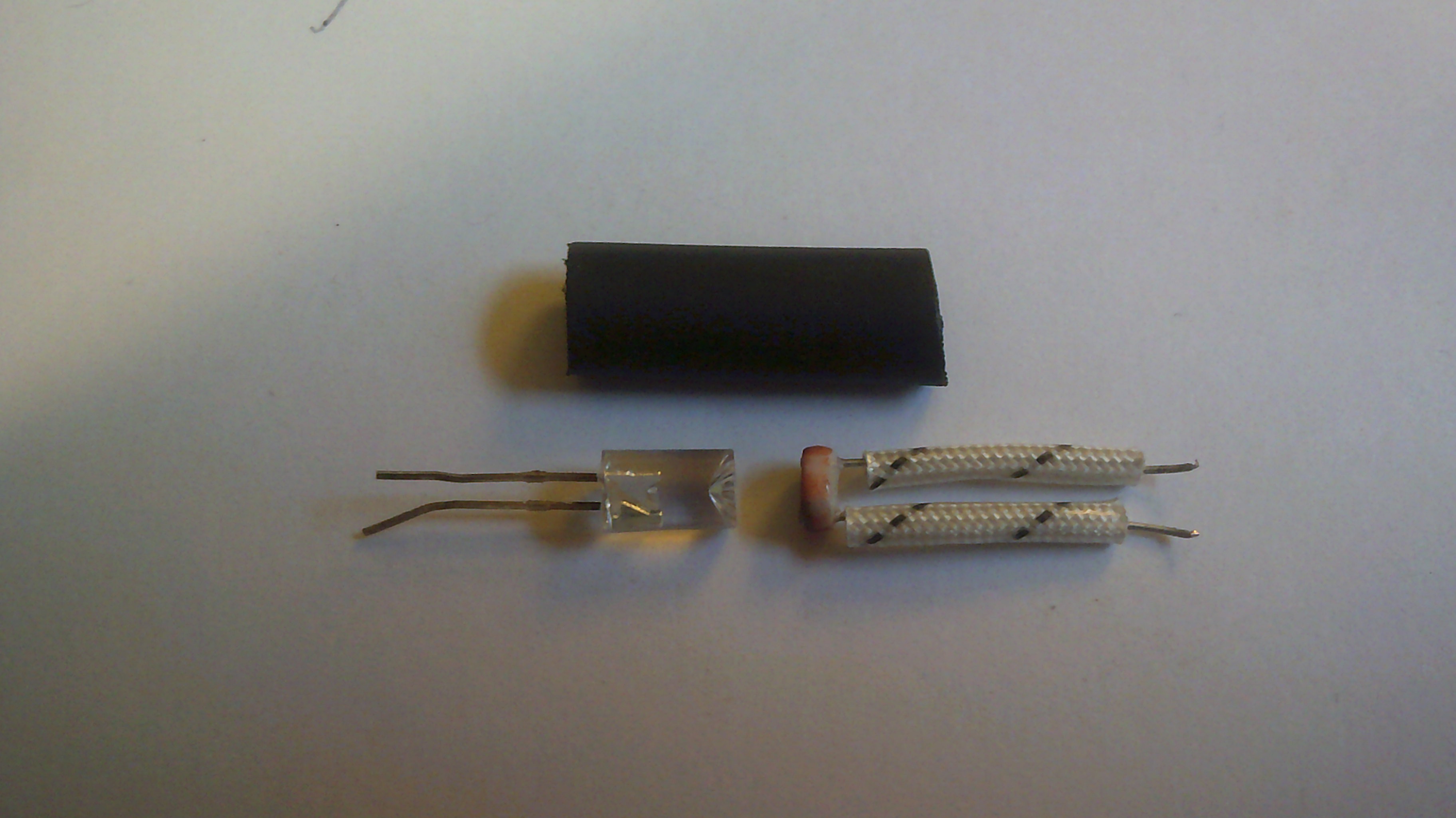
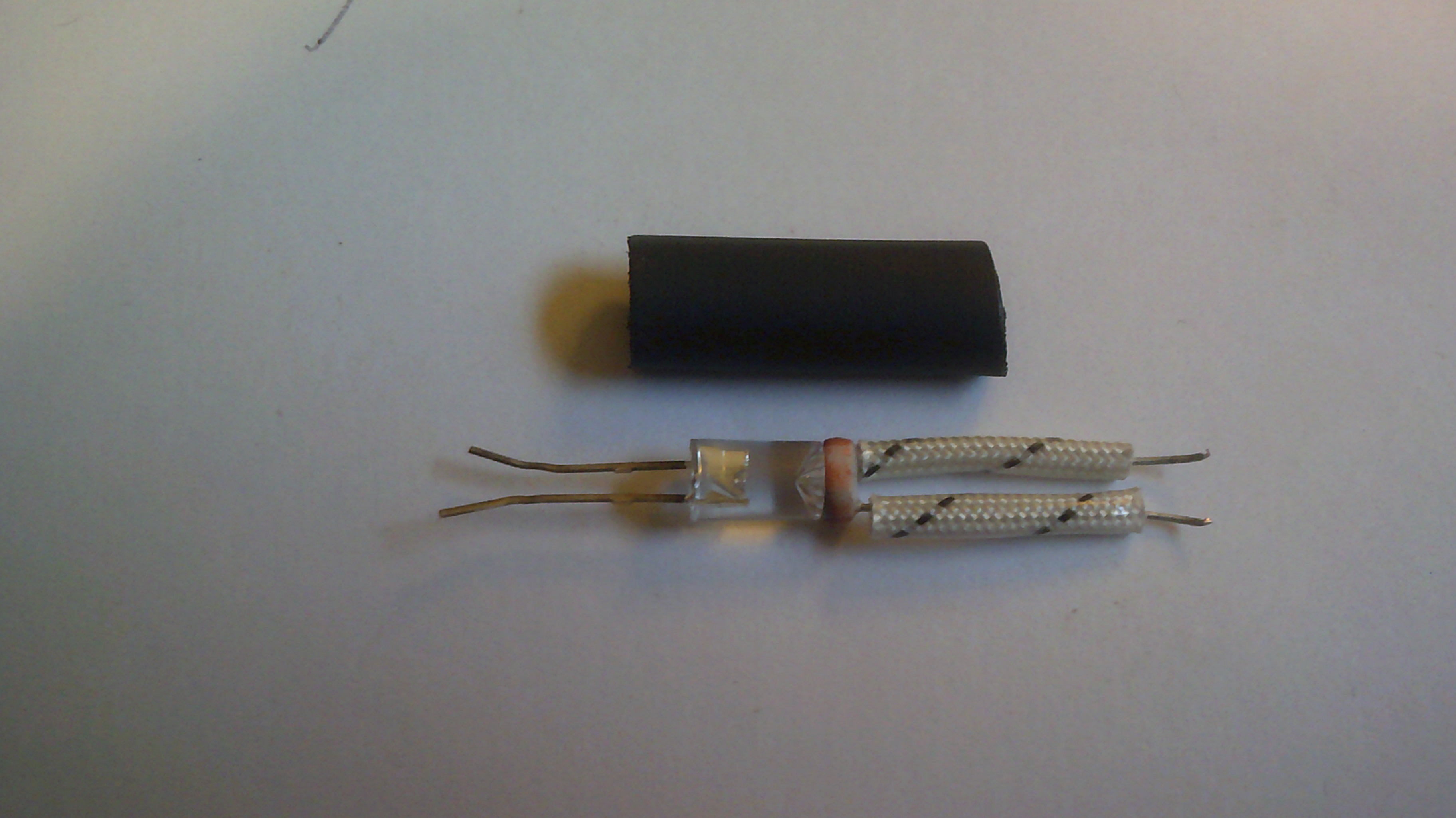
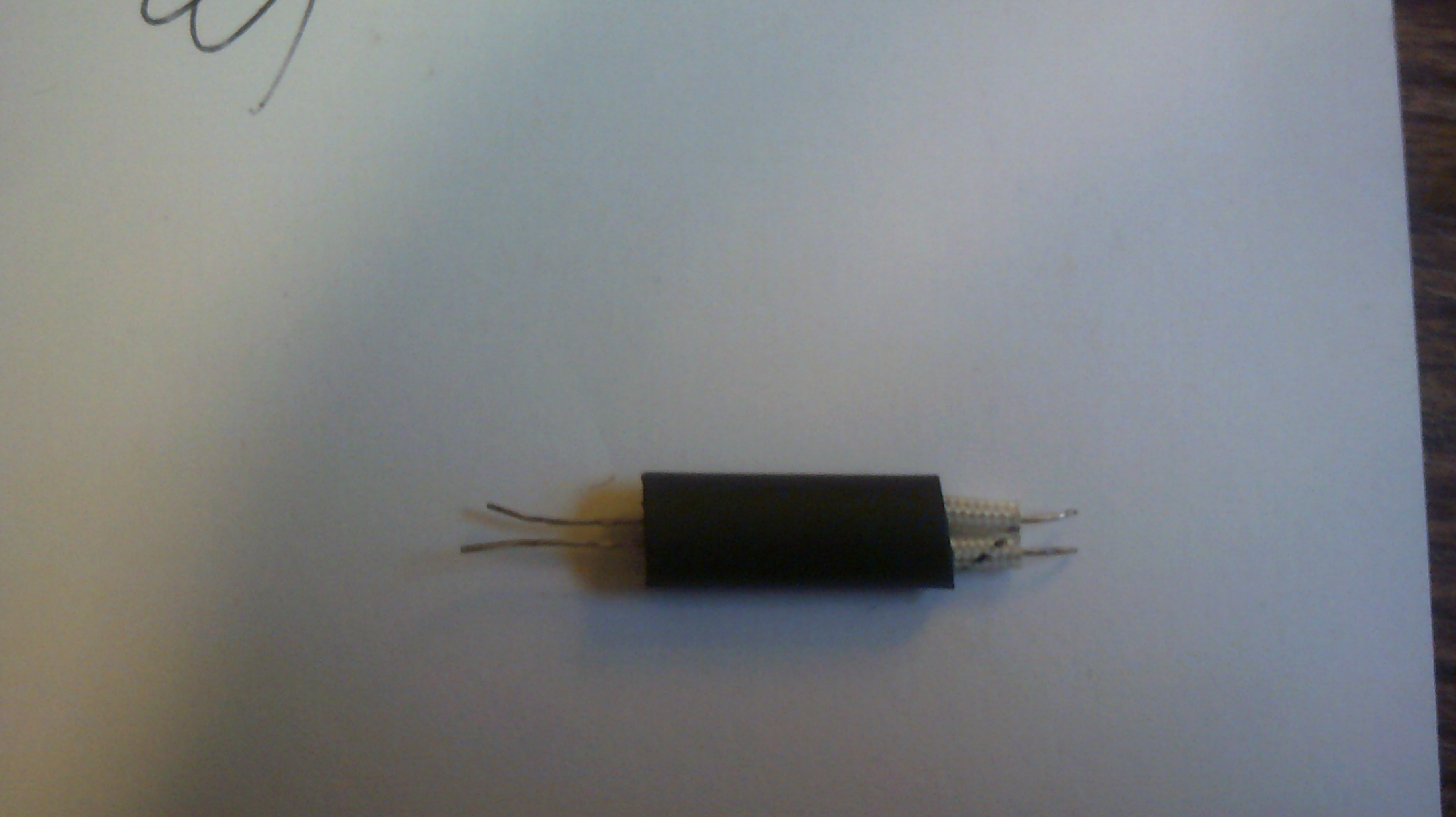
I have decided that even though the relay will work as isolation for the printer signals, I see that it would take a lot of time to perfect and build the number that I need. Sooooo, I am rolling my own opto-couplers. @Morning.Star provided the seed to go this way and it is so simple. The CdS cells are from old style night lights found in area thrift stores and the Leds I already have so take a look at the construction images and smile a little. BTW I have seen this method else where on the internet and it works quite well. With no light the cell has a resistance of 15k ohms and full led light it goes down to 400 ohms. IO and the printer work well with it.

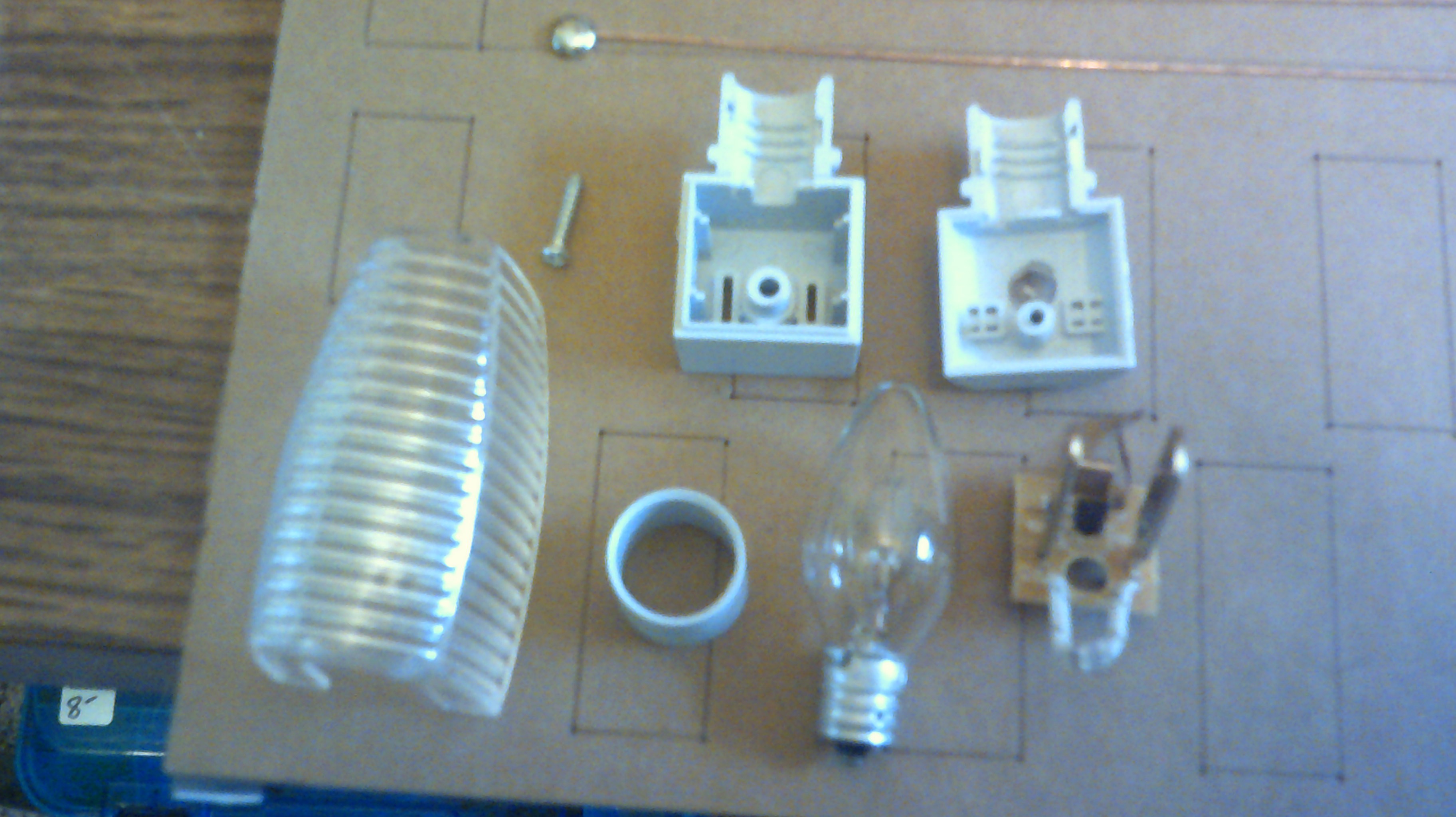
The night lights are being sold cheap as they have old style incandescent bulbs and folks these days want the Led type. Better for me in finding cheap parts to hack with :-)
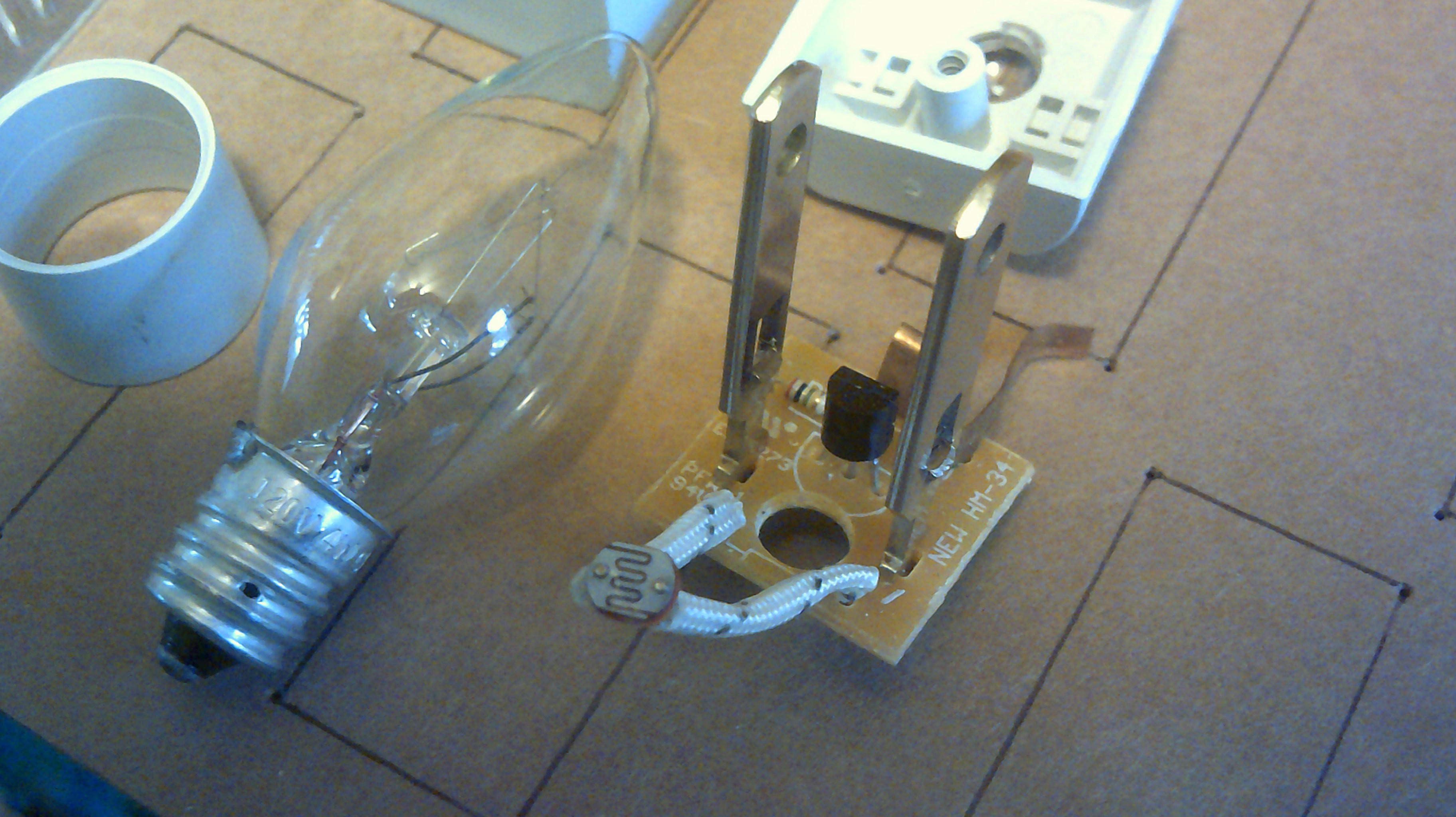
The SCR? and 1meg resistor might find a use later on.
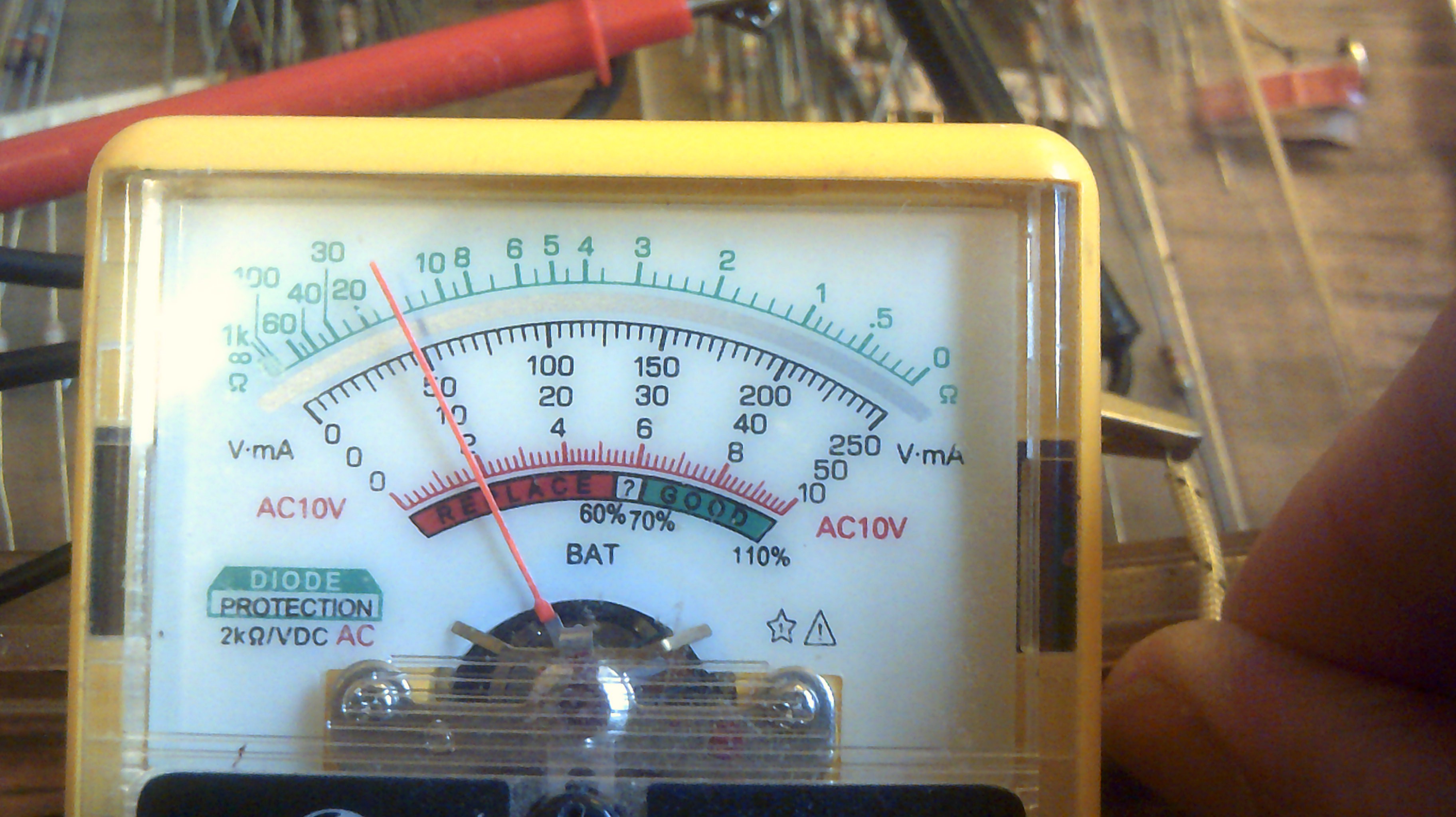
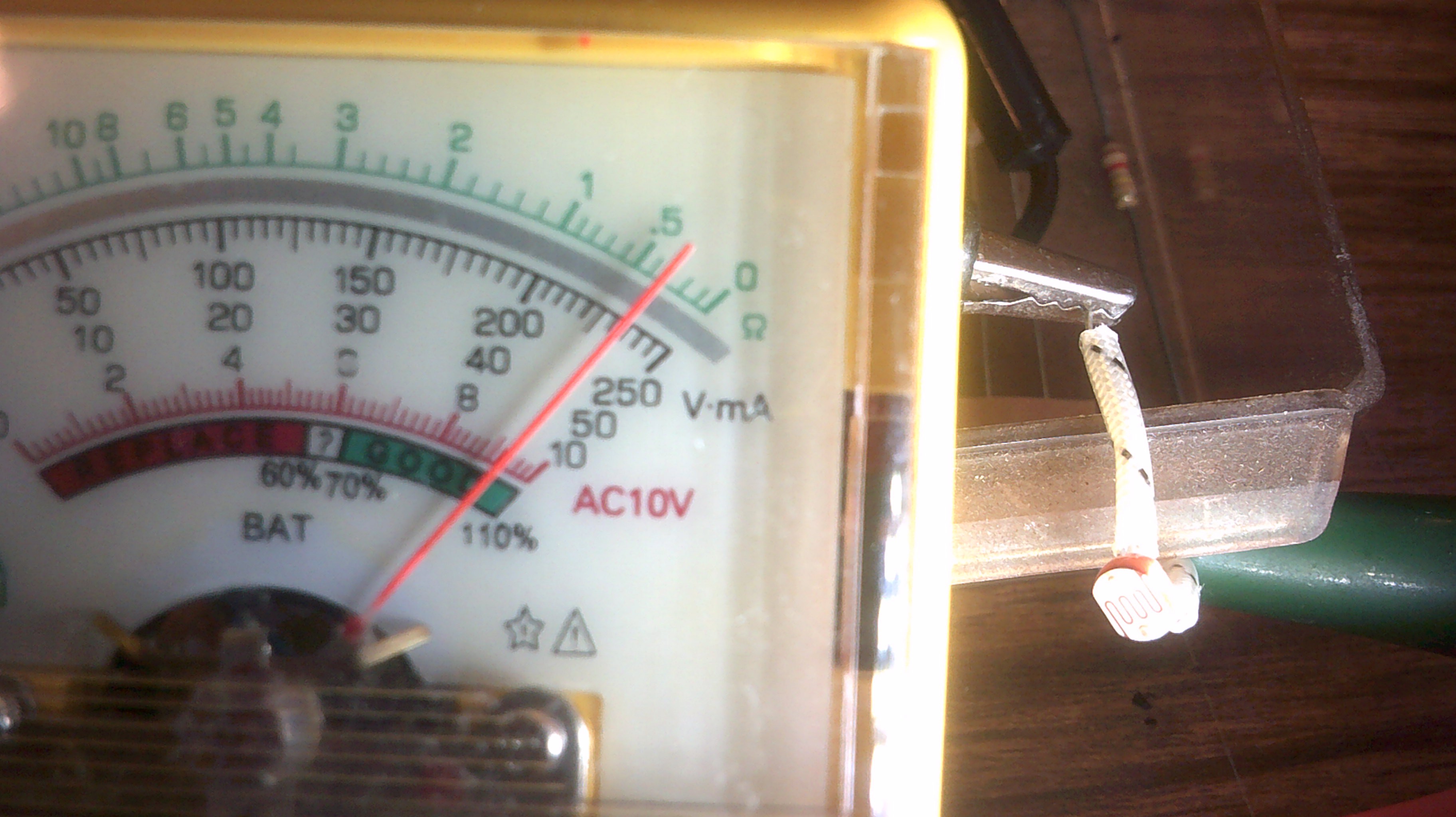
Good swing in resistance.
Here is a very short video of two couplers connected between IO and the printer. No timing or signal level issues :-)
Discussions
Become a Hackaday.io Member
Create an account to leave a comment. Already have an account? Log In.
CdS cells don't have a specific resistance for every cell and level/color of illumination, so much as a range that they almost all tend to fall into some part of. (...not to mention ambient temperature variances!) They're not exactly, er, precise instruments... if you're depending on a very specific resistance for light and dark detection, instead of the previously-mentioned set of ranges, you're going to have a lot of trouble.
If I were doing this, I'd find a way to rig up a comparator circuit and have a CdS on one side and one of those eBay issue blue-box precision-turn pots on the other. Once the two are /roughly/ equal, a bit of hotsnot aka hot glue (or superglue or...) will keep the pot in place for a remarkably long time. Any significant variance in illumination, at that point, will be enough to upset the comparator and make it squawk...
That said, I tend to think in chips, not discrete componentry... I don't know if you can make a comparator easily out of the sort of transistors you're using. I'd use an LM324, probably, as the combined output control for four optocouplers... but, again, that's a level /above/ you right now, and I simply don't know enough to advise on the level at which you're working. Maybe look at old triode circuits and tinker with adapting them to RTL?
Are you sure? yes | no
Using discrete transistors, a comparator is quite easy to do, it's called a differential amplifier :-) (that requires 2 or 3 transistors and some resistors)
Are you sure? yes | no
Time will tell. Have a couple of these now and both work well and the requirements I need to meet are not at all narrow. Just switching the 2 volt signal at the printer and it's working very nicely :-)
Much easier to wire up than the relay ;-)
Are you sure? yes | no