 Peter Lyons
While experimenting with different size ball bearing mods to reduce travel, we didn't have a great test rig set up. I guess ideally you'd have a hotswap MX keyboard at hand and swap in your modded key to do some careful quality control tests. Being low-profile enthusiasts, we have little to no MX gear around here, so our test rig consisted of holding the modded switch in the skeletyl PCB and trying to rotate it where both switch pins would make good contact with the PCB through holes then while not letting that wiggle out of place, try to type. We basically got "it never types" or "it probably types OK" result accuracy.
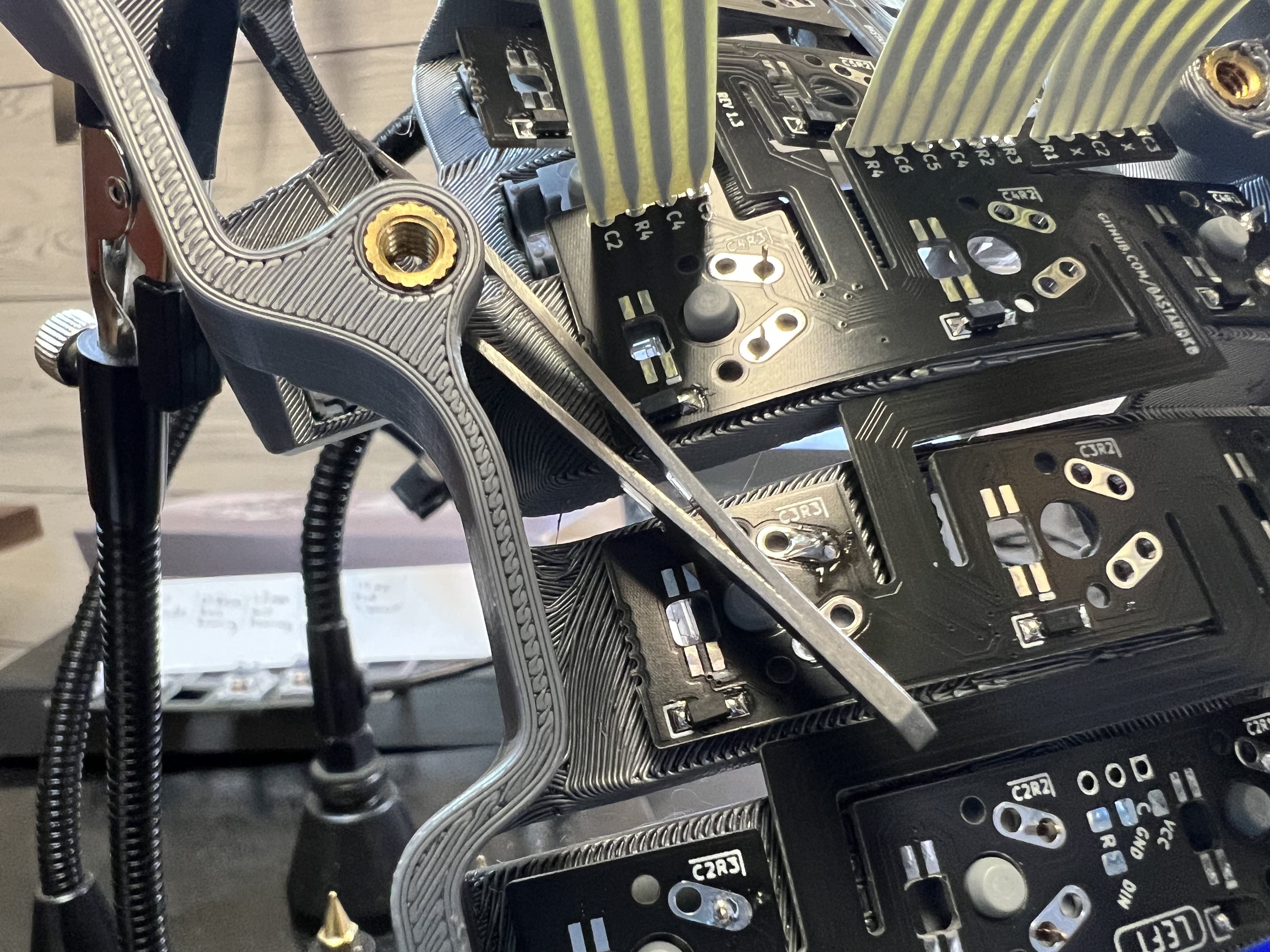
We got a nice shot of the travel reduction of each mod by removing the springs so gravity would leave the stem in the lowest position for the photo. The rightmost switch isn't fully seated into the plate. Sorry about that. I didn't notice until I had already torn down the rig. But the 1.5mm ball bearing and 1.5mm hunk of PLA filament both do exactly the same thing to the stem travel.


So yesterday we proceeded to insert a modded switch into the skeletyl 3D printed case, bend the flexible PCB into position over the post, and solder the first switch into the case. Once that was done, we had a much more reliable setup from which to carefully test for clean typing.
AC went into production line mode opening switches and preparing to work through a full batch of 18 switches, but I insisted we do a round of careful tests first. It turned out to be the right approach because as we tested, we easily found clear double-press misfires with sometimes as much as like 5% probability. So we kind of panicked a bit and soldered I think 3 total switches in: one stock with no modifications, one with a 1.2mm ball bearing, and one with a 1.5mm ball bearing.
The unmodded switch worked without issue. Both of the modded switches had frequent double-fire errors. I got pretty despondent and felt like all this time researching, ordering, waiting for parts, 3D printing custom tools, etc was a waste. I mean, we learned what doesn't work though, right?
So then I had to desolder the modded switches so we could unmod them. I got them out but desoldering is tricky business.

So next there was like a camera pan to a high overhead shot of me in the lab where this project was supposed to yield a choc skeletyl and instead here I am building with unmodified MX switches with a mile of travel and a super high profile like a pleb. So I decided to just finish the build, play around with vial firmware which I haven't used yet, and try it out. If it's OK for me to type on, it will be in theory less janky than my current daily driver hand wired tbkmini.
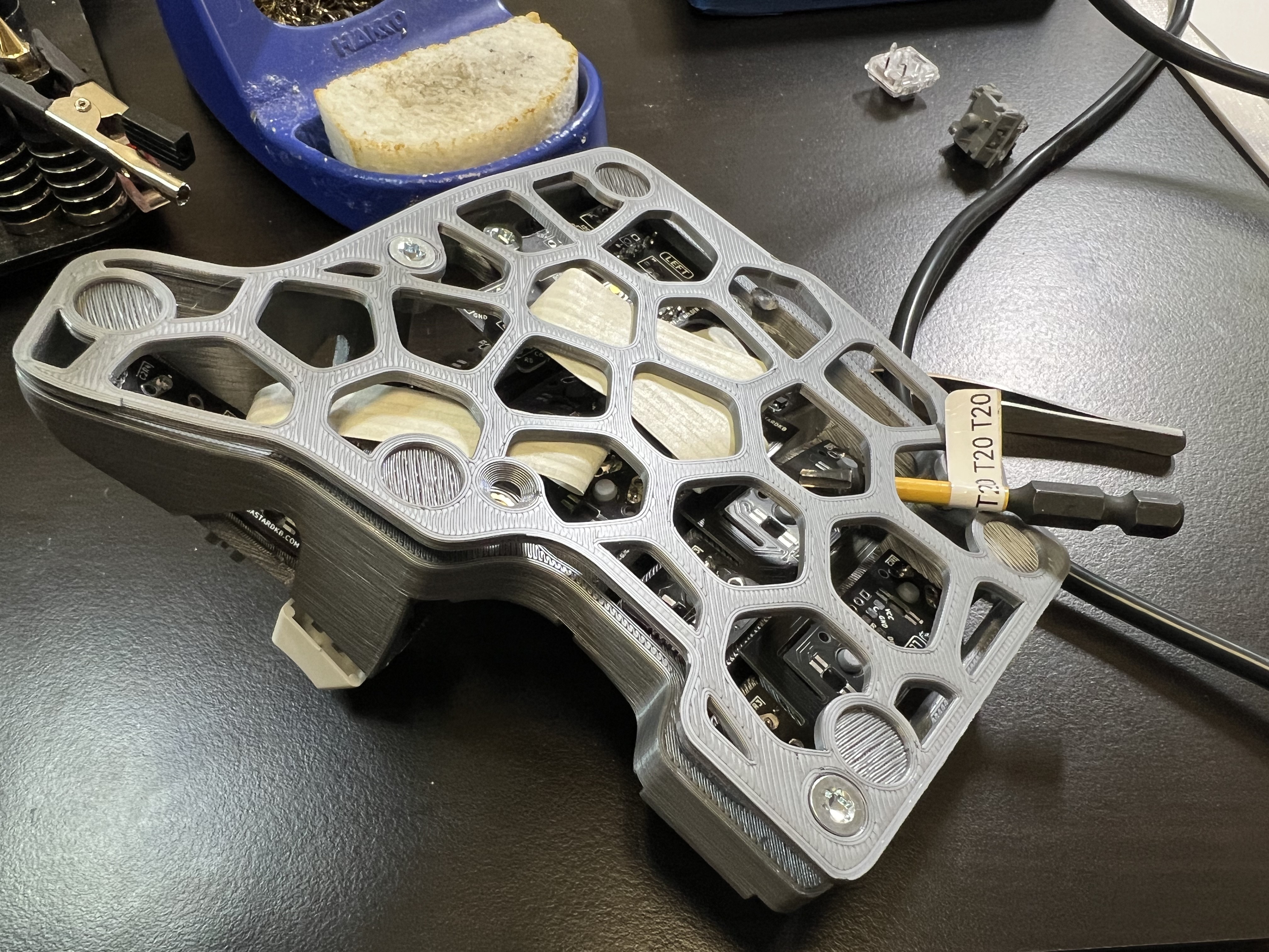
Getting the switches installed, clicked into the "flexible" PCBs and soldered on a skeletyl is hard. Like really hard. Like, it would be easier to hand wire this hard. The "flex" mechanism doesn't really handle the z-axis variation that well. I bent switch pins on a bunch of switches in trying to get the PCB pressed into place.
Eventually I found solutions combining helping hands clamped to the case, and either a tweezer wedged in holding the PCB down or a spring clamp if there is access from the side to place it.

When I got one side finished, I mounted the MCU holder PCB to the case. This was also very tricky to get both ports fully aligned with their holes in the case and both of the threaded inserts exactly below the through holes so the screws can thread in. I eventually got it to work, but this could easily have been 15 minutes of futzing.
When I went to attach the bottom plate, I had another sad trombone moment when I realized I had soldered the ribbon cables to the wrong side of the MCU PCB. I think the electronic connections are still right because the legends lined up, but there's also a chance that the wiring matrix is now messed up and I'll have to adjust the firmware to compensate for that. But in the end, I just bent the ribbon cables a bit closer to the PCB and a bit sharper of an angle than is probably ideal, but the case does now fit and doesn't bulge out at that spot. I could try to fix this before finishing the other half but I think it'll be easier to manage if both halves are symmetric. Plus, I did probably my best ever soldering job on this project and I don't want to mess that up with a bunch of desoldering and resoldering on the ribbon cables.
But I think there's a good chance I may end up selling this one on mechmarket since it's a really nice build if you like MX switches and akko CS silvers in particular.
Discussions
Become a Hackaday.io Member
Create an account to leave a comment. Already have an account? Log In.