Ruslan
Introduction
MODBUS is an industrial protocol developed by MODICON in 1979. The protocol has become very popular due to its simplicity and reliability. Even more than 50 years after the publication of the specification, it remains one of the most popular industrial protocols in the world.
Today, there are a huge number of devices on the market that support this protocol, most of which are for industrial applications. These are sensors, actuators, frequency drives, touch and key operator panels, climate systems, charging controllers for solar battery systems, PLCs, gateways, modems, etc. They are manufactured thoroughly and with high quality, in accordance with industry standards.
Therefore, the ability to connect MODBUS devices to computers and microcontrollers opens up wide opportunities for building advanced and reliable automated systems. From data collection in a smart home system to a whole factory management system.
In this project, I developed a MODBUS gateway that allows you to connect a network segment with MODBUS devices (up to 32 devices) to the control system via a WiFi connection. The number of such gateways is unlimited.
The gateway does not require any MODBUS protocol register settings, because it transparently converts MODBUS RTU packets to MODBUS TCP and vice versa.
To be honest, I developed this project more than 5 years ago for use in my smart home system. Using a MODBUS gateway, I connected an electric meter to the Majordomo smart home system. The gateway has been working fine since then, so I decided to share this project with the community.
MODBUS protocol variations
The first versions of the protocol worked on top of asynchronous serial interfaces (RS 232, and later RS485 and RS422). There are 2 variations of the MODBUS protocol for these interfaces - MODBUS RTU and MODBUS ASCII. The difference between them is that RTU is the binary version of the protocol, and ASCII is the text version. The obvious advantage of MODBUS ASCII is the ease of debugging. But MODBUS RTU uses the bandwidth of the channel 2 times more efficiently. To date, MODBUS ASCII is not used in new devices, it has been completely replaced by MODBUS RTU, so MODBUS ASCII is not supported in the gateway.
With the rapid spread of the TCP/IP protocol stack, there is a need in the industry for a TCP version of this popular industrial protocol. There are 2 protocols for solving this problem: MODBUS RTU and MODBUS RTU over TCP.

MODBUS TCP is the official implementation, which is described in the specification. The difference between MODBUS TCP and MODBUS RTU is that the MBAP Header is added to the beginning of the packet, and the checksum field is not used (because the integrity of the packets is controlled by the TCP protocol).
MODBUS RTU over TCP is a simple transfer of all RTU frames over a TCP connection without making any changes to the frame.

As you can see from the illustration above, both protocols (MODBUS TCP and MODBUS RTU over TCP) can be transparently converted to and from MODBUS RTU. Transaction ID field is used to determine whether the response belongs to the request. Protocol ID field is always 0.
What does the PDU field consist of?
In the MODBUS protocol, there is always 1 master and 1 or more slaves. MODBUS communication always initiates the master. It sends a request to one of the slaves, after which the slave sends its response back to the master.
The MODBUS protocol supports only 2 data types - 1-bit (discrete) and 16-bit (analog). For industrial automation, this is more than enough. This limitation is at the same time a significant simplification that contributed to the widespread use of the protocol.
There are up to 4 register groups inside each Slave device. They are shown in the illustration below:

Discrete Inputs and Coils are 1-bit registers, Inputs and Holding are 16-bit registers. The MODBUS protocol functions that are used to read and write registers are listed on the right.
The PDU field in MODBUS packets consists of 2 parts: Function ID and Data. How they are filled is shown in the illustration below:

The slave device can send an error code in response to the master device. The PDU field in this case consists of 2 parts: Function ID and Error code. How they are filled is shown in the illustration below:

Protocol selection
In the gateway to communicate with the smart home system, I used the MODBUS TCP protocol, because it is supported by all control systems that I have met. MODBUS RTU over TCP I met only in some gateways.
The physical level for connecting the electric meter is RS485. It is an interference-resistant industrial field bus. RS485 is a differential interface, that is, logic 1 or logic 0 is determined by the potential on wire A relative to the potential on wire B. Due to this, external interference is induced on both wires A and B equally, and at the receiver the interference is subtracted from itself. RS485 is used in most devices with MODBUS RTU support.
As a result, the block diagram of my system in terms of working with MODBUS looks like this:

Hardware
The schematic diagram of the gateway is shown below:

It is based on the ESP-07 module on the ESP8266 microcontroller from Espressif.

The module has a built-in WiFi antenna and a connector for connecting an external antenna.
The ADM3485E chip is used to implement the RS485 interface. Any RS485 transceiver with a 3.3V power supply can be used.
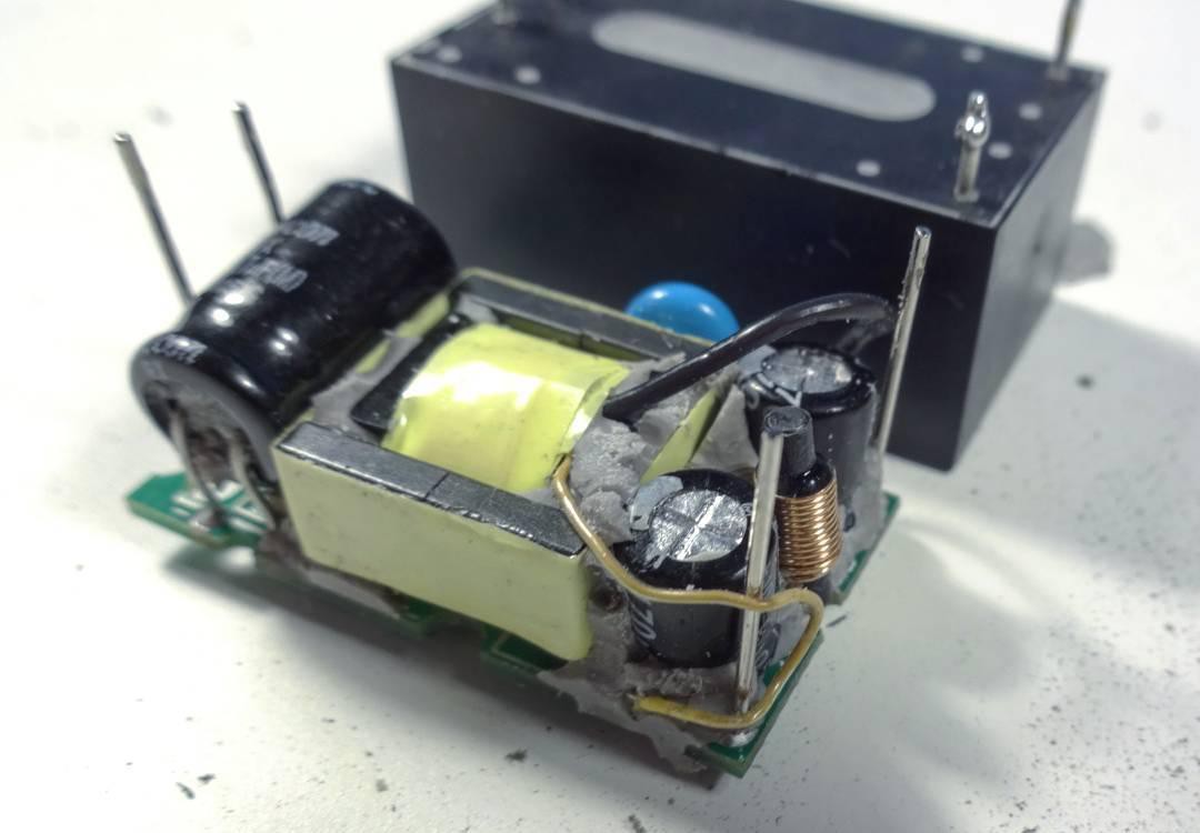
The AC-DC module HLK-PM03 is used to power the gateway from AC voltage.

This is a module with a stabilized output voltage of 3.3V and a power of 1W. The input voltage range is quite wide: from 100 to 240V. Inside the HLK-PM03 is a full-fledged switching power supply in a sealed housing and with galvanic isolation. I disassembled one of these, here's what it looks like without the case:
There is 1 LED on the board that lights up when the gateway is powered.
The P2 connector is for flashing the ESP8266 (a USB to UART adapter is required). To switch the microcontroller to BOOT mode, you must install the JP1 jumper and press the SW1 (RESET) button.
Jumper JP2 connects a 120 ohm terminating resistor to the RS485 bus. Install this jumper if you have a long RS485 bus and the gateway will be located at one end of the bus.
Fuse F1 - self-resetting for a current of 0.1A.
Fuses F2 and F3 protect against the flow of high current through the bus between devices. Rating - 0.1A.
I use 0 ohm resistors as jumpers because my gateway board routing is single layer.
The board design is made in KiCAD. The 3D visualization of the board in KiCAD looks like this:

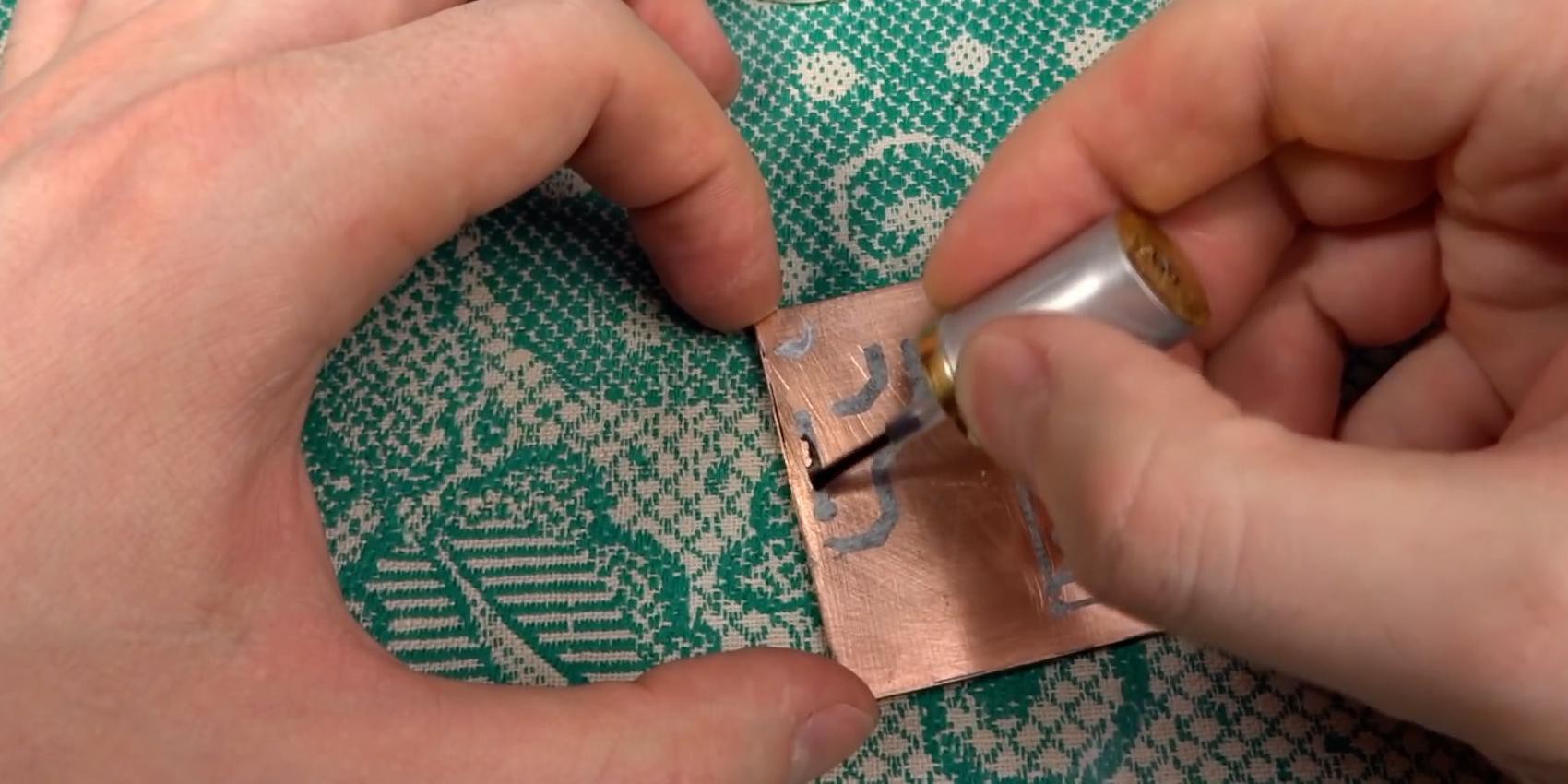
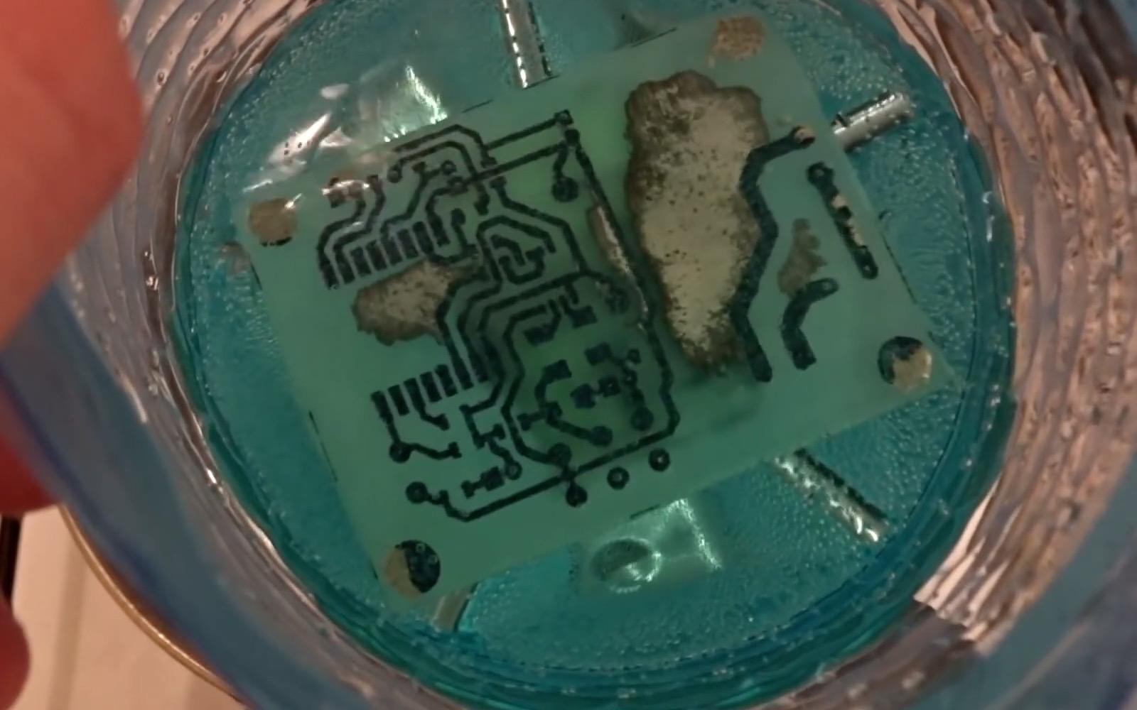
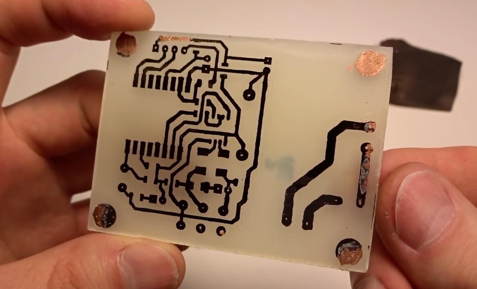
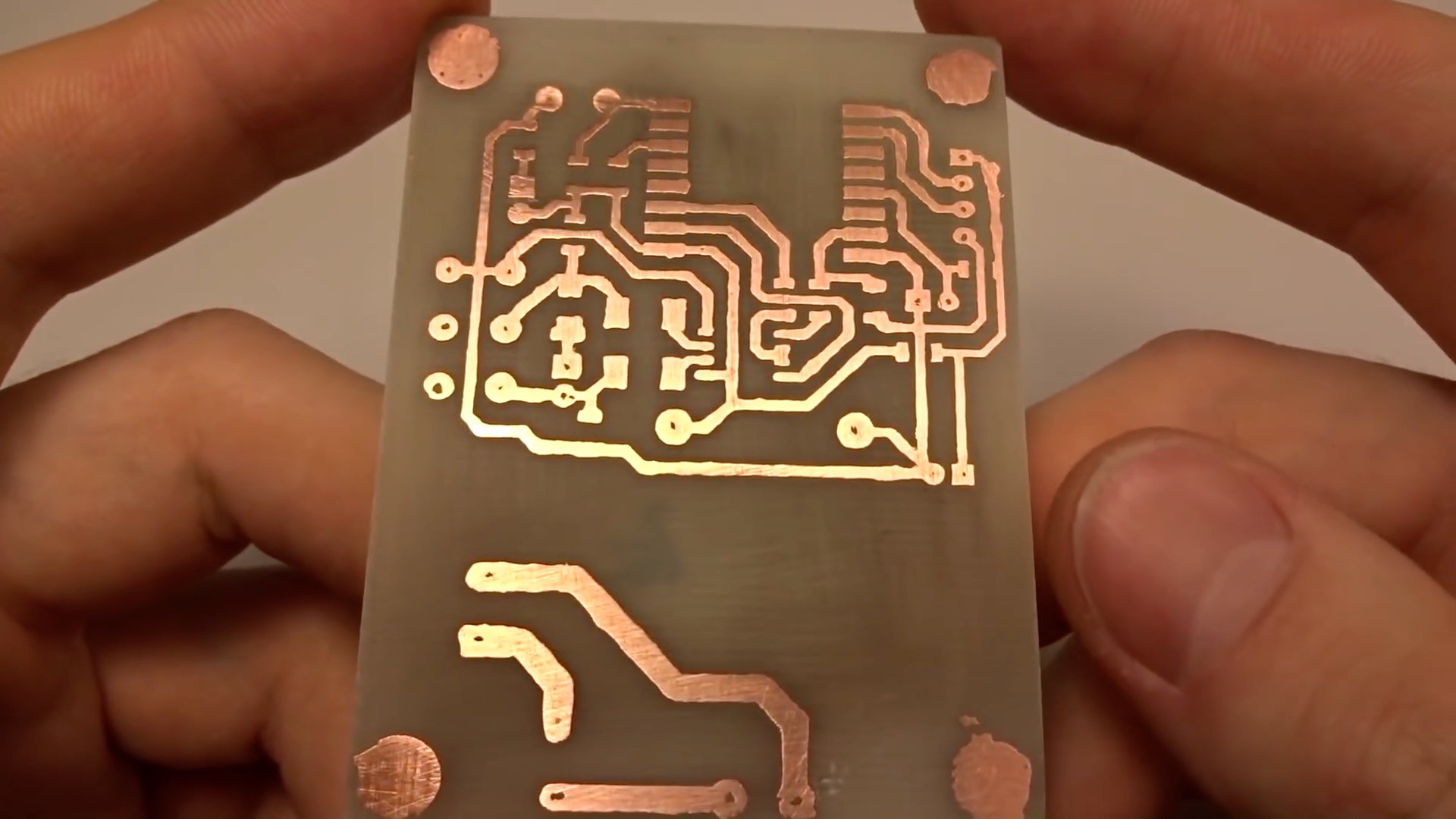
I made PCB myself using the technology of applying laser printer toner to copper before etching.
PCB manufacturing process:


Another way to make PCB is CNC milling (you need to remove the copper layer in the high voltage part of the PCB).

But I recommend ordering quality boards from special companies, such as PCBWAY. https://www.pcbway.com/
Firmware
I flashed NodeMCU firmware to ESP8266. This firmware has a built-in LUA program interpreter. The gateway logic is implemented by the LUA script, which you can find in the “files” section of the project. The script is very short, less than 200 lines.
Before uploading the script to the gateway, you need to change the configuration constants at the top of the script:

After powering up the gateway, it attempts to connect to the WiFi network. In the future, if there was a disconnection from the network, the gateway will try to connect to it again.
After a successful connection, the MODBUS TCP server starts and waits for the client to connect. Further, all requests received from the client are converted to the MODBUS RTU frame format and sent to the RS485 port. Frames received via RS485 are converted back and sent via MODBUS TCP to the client.
According to the MODBUS specification, communication is always initiated by the master (MODBUS TCP client) and it sends all requests sequentially. Before sending another request, it must wait for a response or wait for the response timeout to expire. However, some systems may send 2 requests without waiting for a response. This occurs when the system tries to send write request while read is in progress. To avoid conflicts in this case, the gateway buffers 1 request and if the gateway receives 2 requests at once, the second one will be sent to RS485 only after receiving a response or after a timeout.
Installation and setup
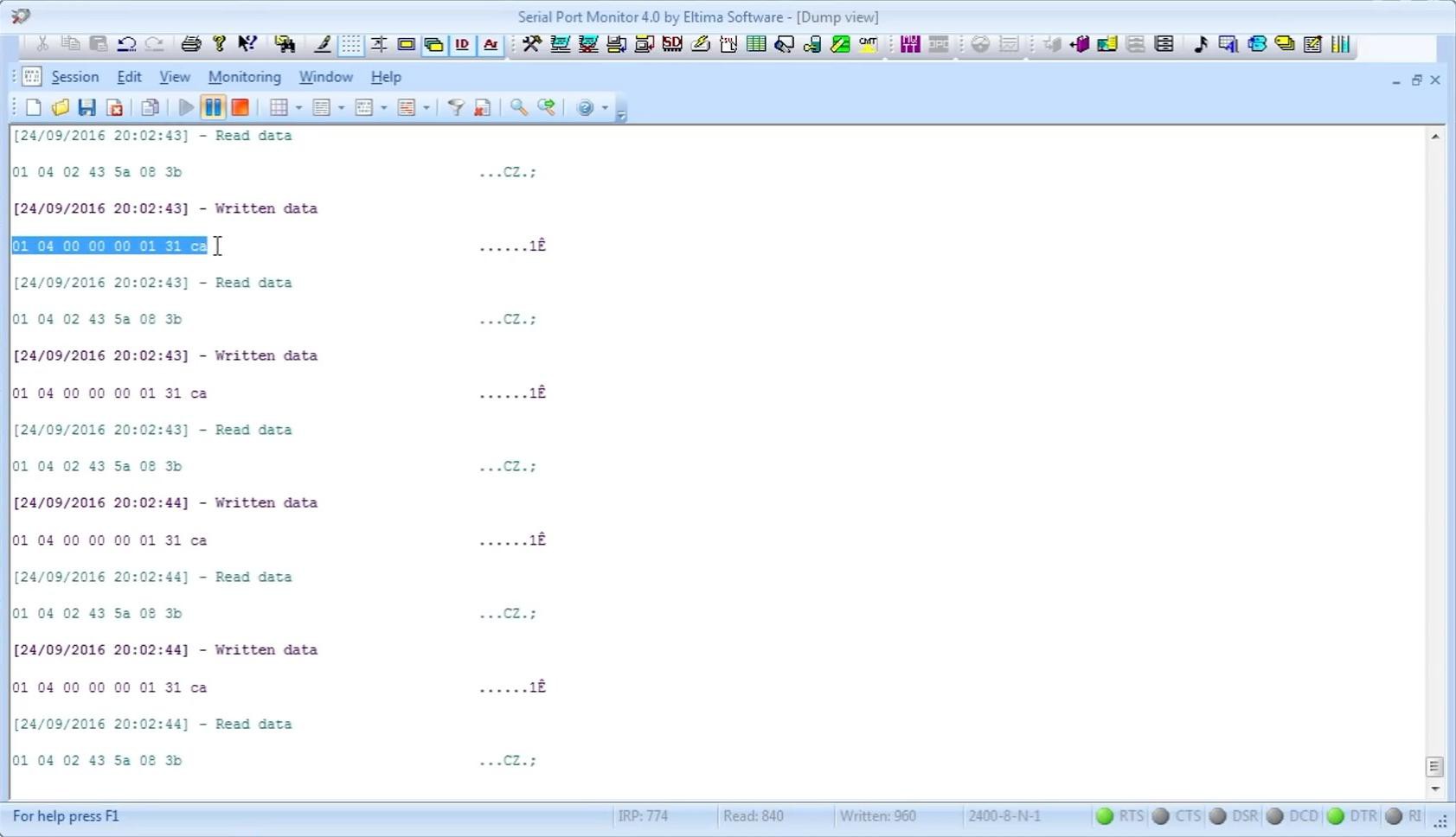
When debugging communication, it is useful to know what is happening on the RS485 bus. I recommend using a logic analyzer or a USB-RS485 adapter for this. With it, you can use terminal programs to see what is transmitted on the bus.

You can also use sniffer programs for COM ports (for example, Serial Port Monitor).
For monitoring on the MODBUS TCP side, I recommend using a sniffer for IP networks WireShark. It can visually display MODBUS frames:

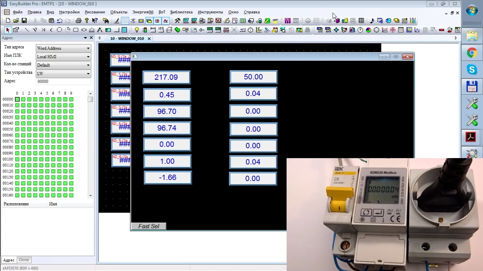
To begin with, I tested communication through the gateway using EasyBuilder Pro (Weintek's operator panel configuration and simulation software).
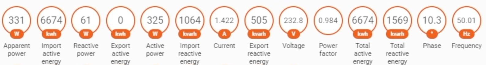
Using the table of registers from the documentation for the electric meter, I was able to read the measured parameters from the meter (voltage, current, power, etc.):
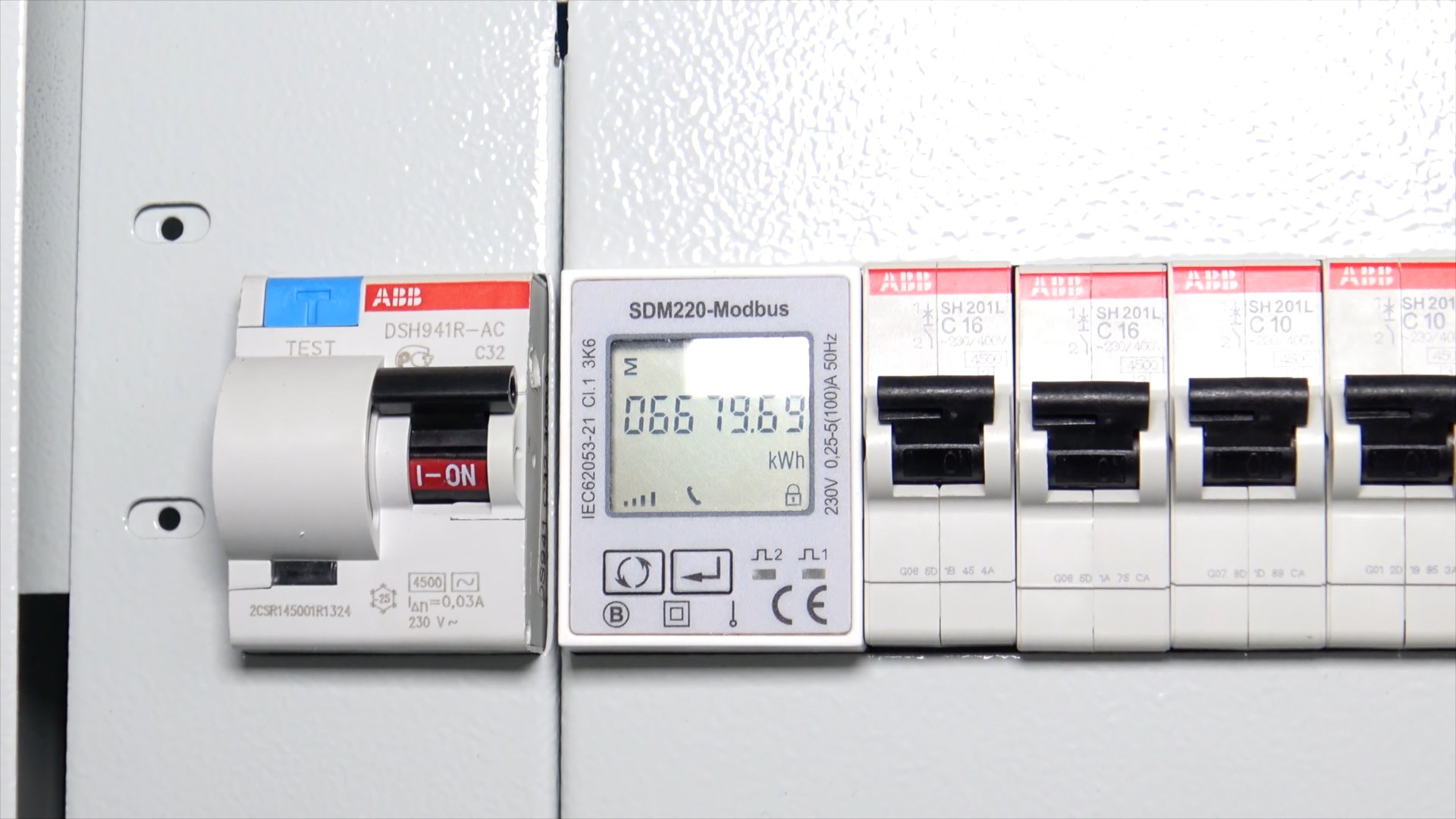
After successful testing, I installed an electric meter and a gateway inside the electrical panel. My electrical panel is metal, so I brought the WiFi antenna outside.

Interestingly, during communication with the electricity meter (SDM220), the handset symbol at the bottom of the display lights up on its screen.
After setting up the same meter registers in the smart home system (Majordomo), the following result was obtained:
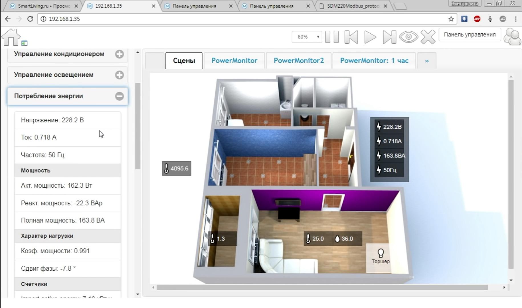
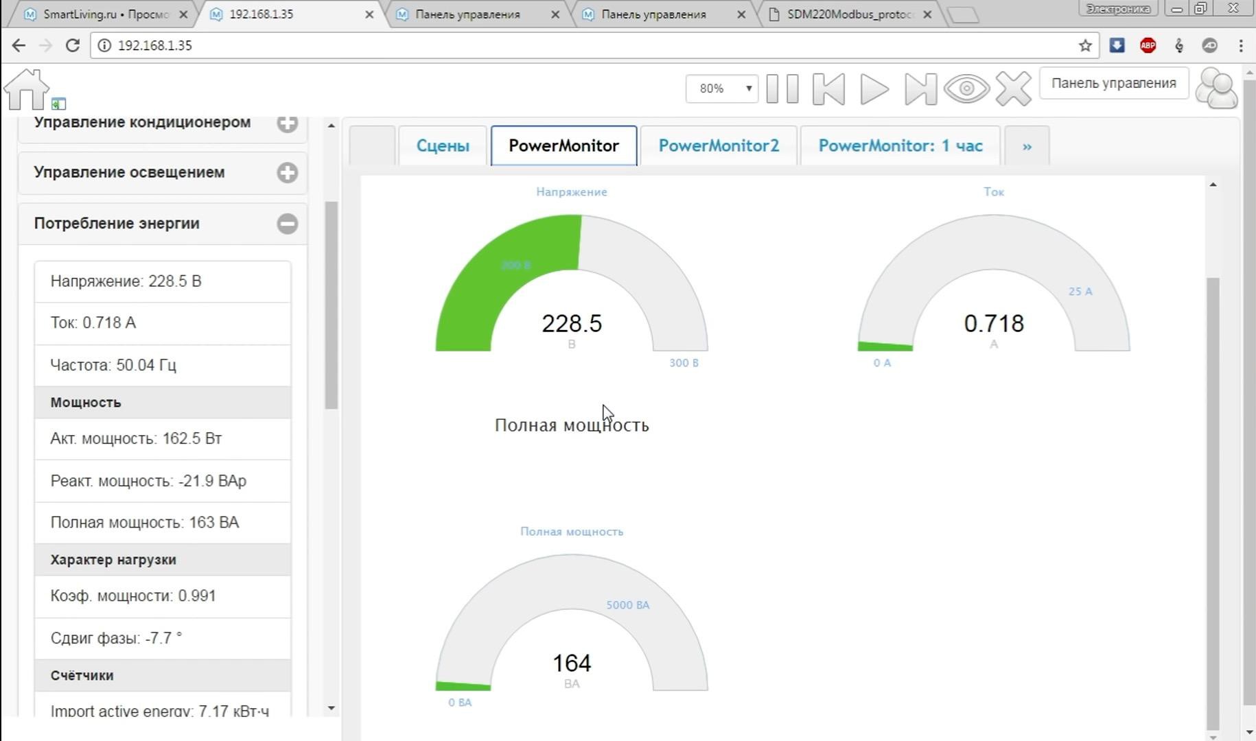
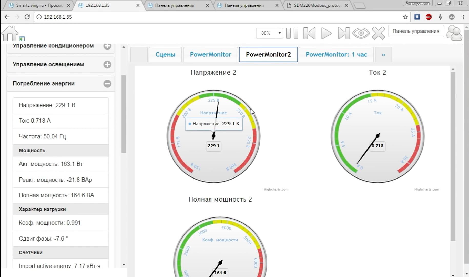
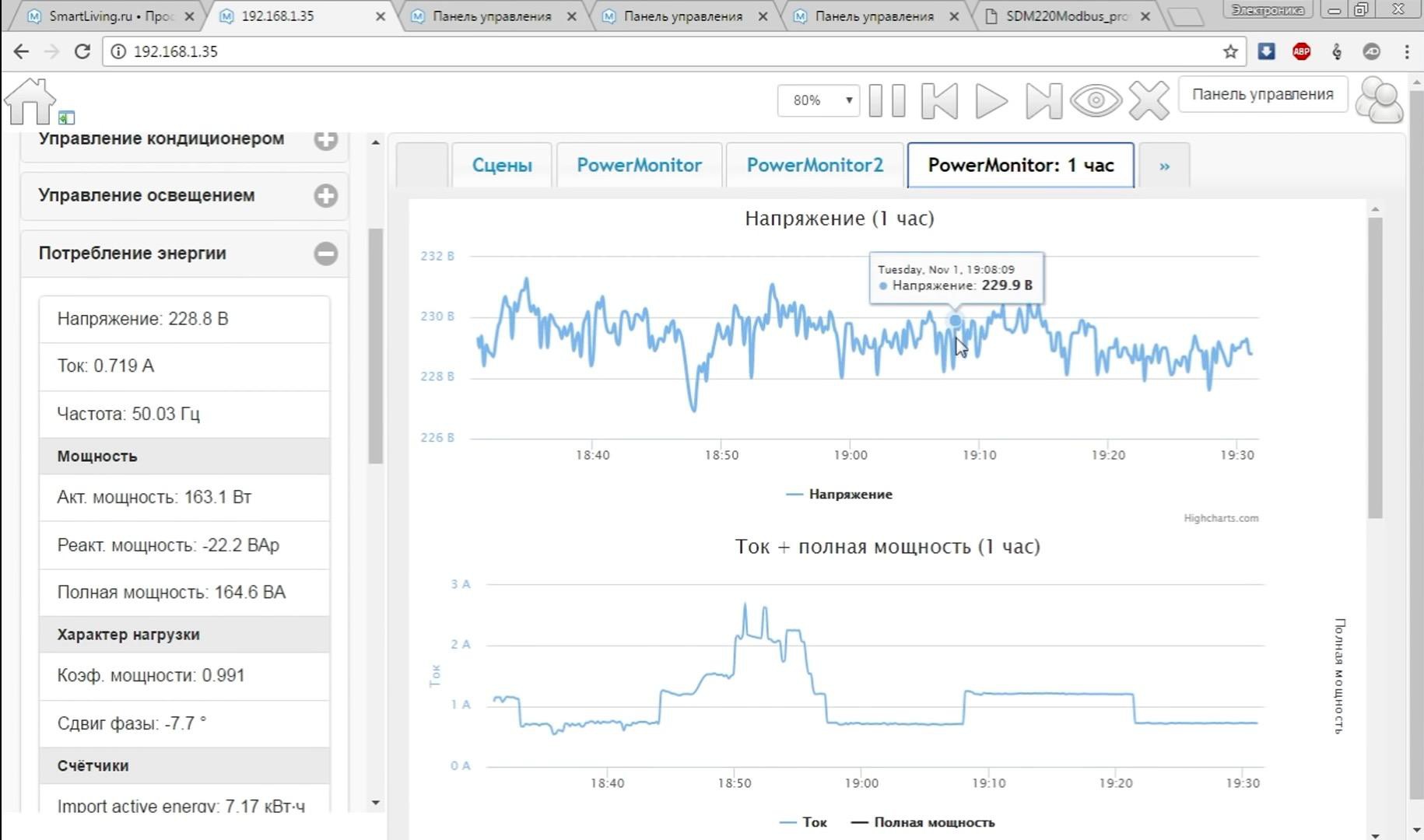
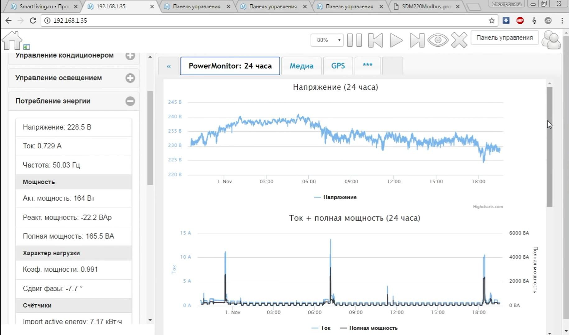
Now in the smart home system, I can monitor the parameters of the electrical network at home!
I also tested the gateway with HomeAssistant. Everything works great!